You are using an out of date browser. It may not display this or other websites correctly.
You should upgrade or use an alternative browser.
You should upgrade or use an alternative browser.
Interesting observation using Castrol Edge Full Syn 0W-16
- Thread starter Hermann
- Start date

- Joined
- Nov 2, 2021
- Messages
- 1,116
I wouldn’t have the slightest idea. Guess whatever goes into the additive pack.
Some interesting graphs in that paper. Things that stand out to me.Oil is also crucial in the boundary lubrication regime, and unlike in the hydrodynamic lubrication regime, the viscosity becomes directly related to wear in the boundary lubrication regime, as opposed to having minimal or no effect on wear if it is above a certain minimum in the hydrodynamic lubrication regime.
Here are the figures in the paper on engine shear rates:
https://www.semanticscholar.org/pap...aker/77276daaebf4d66b9f51c9581e9845f15eb0b72d
1) Figure 2 - As we all know, MOFT in journal bearings increases as the viscosity increases. Viscosity headroom could matter.
2) Figure 3 - why is the film thickness 0 at 0 deg crank angle (TDC), but not 0 again at the next TDC at 360 deg? Is 0 deg TDC assuming a combustion event that takes the MOFT away on the top ring? Also, if the engine RPM is 2500 or higher the MOFT on the top ring is actually higher and about 2u and higher. Is a lot of idling bad for ring wear? ... could be.

3) Figures 4 and 6 - even though the peak shear rates are high for the rings and cam lobe/followers the duration is very short so the wear period per rev is also short. As mentioned before, when the shear rates are high which causes some added decrease in the HTFS and MOFT, the AF/AF additives have to kick in (film strength vs film thickness). And rings and cams/followers are made with materials and hardened to resist wear because they obviously have some metal-to-metal contact when in the boundary lubrication realm.
0° denotes TDC firing and 360° denotes TDC exhaust. There is a lot more load on the piston during firing. Minimum oil-film thickness (MOFT) for a given oil viscosity decreases with increasing load and decreasing speed (Stribeck curve).Some interesting graphs in that paper. Things that stand out to me.
1) Figure 2 - As we all know, MOFT in journal bearings increases as the viscosity increases. Viscosity headroom could matter.
2) Figure 3 - why is the film thickness 0 at 0 deg crank angle (TDC), but not 0 again at the next TDC at 360 deg? Is 0 deg TDC assuming a combustion event that takes the MOFT away on the top ring? Also, if the engine RPM is 2500 or higher the MOFT on the top ring is actually higher and about 2u and higher. Is a lot of idling bad for ring wear? ... could be.
3) Figures 4 and 6 - even though the peak shear rates are high for the rings and cam lobe/followers the duration is very short so the wear period per rev is also short. As mentioned before, when the shear rates are high which causes some added decrease in the HTFS and MOFT, the AF/AF additives have to kick in (film strength vs film thickness). And rings and cams/followers are made with materials and hardened to resist wear because they obviously have some metal-to-metal contact when in the boundary lubrication realm.
Yes, obviously if there is no motion the MOFT would essentially go to zero. Guess the load on the rings from the combustion is expanding the rings more against the cylinder walls is what that graph shows. It's not so much the load/force on the piston dome, but the high pressure getting behind and trying to expand the top ring against the cylinder wall.0° denotes TDC firing and 360° denotes TDC exhaust. There is a lot more load on the piston during firing. Oil-film thickness for a given oil viscosity decreases with increasing load and decreasing speed (Stribeck curve).
No, it has nothing to do with the combustion pressure expanding the rings if any such thing is happening at all.Yes, obviously if there is no motion the MOFT would essentially go to zero. Guess the load on the rings from the combustion is expanding the rings more against the cylinder walls is what that graph shows. It's not so much the load/force on the piston dome, but the high pressure getting behind and trying to expand the top ring against the cylinder wall.
It's Newton's third law (action–reaction principle). When the piston applies a load on the oil film, there is an equal but opposite force applied by the oil film on the piston. As this force increases, the oil film gets thinner and eventually squeezed out. The same law also applies to the action–reaction forces between the piston and combustion gases. It is the same phenomenon in the bearings: when you tow, the load on the bearings will increase and the MOFT will get smaller. Obviously, no combustion gases are involved there.
The piston rings float in the piston ring grooves, so if there is a huge side force on the piston, the rings are not going to see any of that force because they float in the ring grooves. The force of the ring face on the cylinder walls (when there is no combustion) is a function of the ring spring tension/pressure. When a piston is at TDC, you can move the piston around within it's clearance to the cylinder, and the rings will remain against the cylinder walls at the force from the compressed ring spring tension action. What's going on between the piston skirt and cylinder wall is different than what's going on between the ring face and cylinder wall when there is no combustion pressure.No, it has nothing to do with the combustion pressure expanding the rings if any such thing is happening at all.
It's Newton's third law (action–reaction principle). When the piston applies a load on the oil film, there is an equal but opposite force applied by the oil film on the piston. As this force increases, the oil film gets thinner and eventually squeezed out. The same law also applies to the action–reaction forces between the piston and combustion gases. It is the same phenomenon in the bearings: when you tow, the load on the bearings will increase and the MOFT will get smaller. Obviously, no combustion gases are involved there.
It's a fact that when the A/F mixture explodes there is a huge amount of pressure in the head dome and on the top of the piston. That gas pressure also gets behind the top ring and tries to expand the ring, and forces the ring face much harder against the cylinder wall as the piston is moved downward in the power stroke. That's probably what they are referring to as the "squeeze effect" in Figure 3 of that paper. Do some research on how piston rings behave, and how they react when the A/F explodes during the power stroke.
Last edited:
The top piston ring expands during combustion. Lots of info on the subject matter if you search.
https://courses.washington.edu/engr.../UofWindsorManual/Piston and Piston Rings.htm
"When the air-fuel mixture is ignited, pressure from combustion gases is applied to the piston head, forcing the piston toward the crankshaft. The pressurized gases travel through the gap between the cylinder wall and the piston and into the piston ring groove. Combustion gas pressure forces the piston ring against the cylinder wall to form a seal. Pressure applied to the piston ring is approximately proportional to the combustion gas pressure."
Last edited:
Detailed paper on ring behavior.
Paper PDF Link
Plus another good reference showing diagram of how the combustion gas pressure gets behind the top compression ring. Note the gas force expanding the ring outward into the cylinder wall, even on the compression stroke before combustion. On the down stroke the combustion pressure puts even more gas force on the top ring.
https://www.riken.co.jp/english/pistonring/piston/basic.html
Last edited:
The reason for the smaller MOFT at 0° firing vs. 360° TDC exhaust is not the ring expansion—it is the higher load. See Figure 2 in my link above for the con-rod bearings, where the same phenomenon occurs. It is more pronounced at the rings because the speed goes to zero and the geometry (eccentricity etc.) is less forgiving.
Moreover, any expansion of the rings would actually increase the minimum oil-film thickness (MOFT), not decrease it. That is because the eccentricity (wobbling) is reduced when the rings expand, and the MOFT is inversely proportional to the eccentricity (wobbling), as more wobbling squeezes out the oil film more.
Nevertheless, these are theoretical calculations, and I doubt that the authors bothered to factor the ring expansion into them.
Nevertheless, these are theoretical calculations, and I doubt that the authors bothered to factor the ring expansion into them.
Exactly what load on the top ring are you talking about? The load on the piston and connecting rod and small and big end bearings are from the combustion force pushing the piston down, but that motion doesn't cause the rings to push harder against the cylinder walls. The only thing making the radial force and load on the rings higher above the ring spring tension is the gas pressure in the cylinder pushing the ring face harder against the cylinder wall.The reason for the smaller MOFT at 0° firing vs. 360° TDC exhaust is not the ring expansion—it is the higher load. See Figure 2 in my link above for the con-rod bearings, where the same phenomenon occurs. It is more pronounced at the rings because the speed goes to zero and the geometry (eccentricity etc.) is less forgiving.
Now you're saying the rings expand ... how so?Moreover, any expansion of the rings would actually increase the minimum oil-film thickness (MOFT), not decrease it. That is because the eccentricity (wobbling) is reduced when the rings expand, and the MOFT is inversely proportional to the eccentricity (wobbling), as more wobbling squeezes out the oil film more.
Nevertheless, these are theoretical calculations, and I doubt that the authors bothered to factor the ring expansion into them.
If you look closely at a compression piston ring, the face isn't perfectly square and has a slight radius on the face to account for the small amount of wobble due to the ring to groove clearance so the ring can seal even if it wobbles/twists in the groove as the piston moves up and down. So regardless of the position of the ring in the piston groove, the face contact patch basically remains constant.


Here's a study of different face profile shapes of the compression ring had how that effects the lubrication of the top compression ring. Can download the full PDF too.
https://www.mdpi.com/2075-4442/8/8/83/htm
https://www.mdpi.com/2075-4442/8/8/83/htm
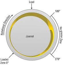
What I am saying is that MOFT and the clearance between the cylinder wall and ring are different things. In a bearing, it looks like this:Now you're saying the rings expand ... how so?
I doubt the authors assumed a varying ring–wall clearance. The effect of a smaller MOFT at combustion TDC vs. exhaust TDC is being caused by the load on the piston increasing by the combustion and the speed of the piston decreasing as it approaches the top dead center, not by the ring expansion. A similar but less dramatic effect is seen at the con-rod bearings in the authors' figures.
Last edited:
I don't really know what you're trying to convey here. I know how a journal bearing operates, been discusding them for years on BITOG. You seem to think that I believe the oil film in a journal bearing and the oil film between the compression ring face and cylinder wall acts the same way - I don't. And the use of the term MOFT just doesn't mean inside a journal bearing. It can also mean the minimum oil film thickness between any moving parts/surfaces when the oil film varies in thickness due to operating conditions.What I am saying is that MOFT and the clearance between the cylinder wall and ring are different things. In a bearing, it looks like this:
Nobody said, including me, that there was a varying ring to wall clearance - how would that be possible? The rings are always in conract with the cylinder wall due to their spring tension. I think you're misinterpreting some of the things I'm saying for some reason.I doubt the authors assumed a varying ring–wall clearance.
Exactly what loads are you talking about? You don't think there is any ring expansion? Maybe you think "expansion" means something else in this case, like thermally (?).The effect of a smaller MOFT at combustion TDC vs. exhaust TDC is being caused by the load on the piston increasing by the combustion and the speed of the piston decreasing as it approaches the top dead center, not by the ring expansion.
So you don't believe what the papers say about the high pressure combustion gas pushing the top ring outward (trying to increase its diameter) and forcing it harder against the cylinder wall? Just like in a journal bearing, a high load can reduce the film thickness by squeezing the oil out between the ring and wall - that's probably what the "squeeze effect" comment in the figure was referring to.
The loads on the journal bearing caused by the rod/piston stroke motion inertia and the highest load from the combustion power stroke are in the bearing's radial direction, and causes the film thickness (MOFT) to vary by squeezing oil out the open sides of the bearing.A similar but less dramatic effect is seen at the con-rod bearings in the authors' figures.
The load on the piston rings from the same stroke motion inertia only acts in the direction perpendicular to the ring face. What causes the increased load on the ring face to wall at combustion TDC is the 1000s of PSI on the back side of the ring, as the many diagrams posted show. More force on the ring face is going to squeeze out oil and reduce the film thickness, especially because of how thin the ring face is.
What you're missing is the directional nature of these forces. The force due to the expansion of the ring is negligible in comparison to the force applied on top of the piston by the gas pressure multiplied by the sine etc. of the angle involved to get the resultant component. Here is the full analysis of the forces:I don't really know what you're trying to convey here. I know how a journal bearing operates, been discusding them for years on BITOG. You seem to think that I believe the oil film in a journal bearing and the oil film between the compression ring face and cylinder wall acts the same way - I don't. And the use of the term MOFT just doesn't mean inside a journal bearing. It can also mean the minimum oil film thickness between any moving parts/surfaces when the oil film varies in thickness due to operating conditions.
Nobody said, including me, that there was a varying ring to wall clearance - how would that be possible? The rings are always in conract with the cylinder wall due to their spring tension. I think you're misinterpreting some of the things I'm saying for some reason.
Exactly what loads are you talking about? You don't think there is any ring expansion? Maybe you think "expansion" means something else in this case, like thermally (?).
So you don't believe what the papers say about the high pressure combustion gas pushing the top ring outward (trying to increase its diameter) and forcing it harder against the cylinder wall? Just like in a journal bearing, a high load can reduce the film thickness by squeezing the oil out between the ring and wall - that's probably what the "squeeze effect" comment in the figure was referring to.
The loads on the journal bearing caused by the rod/piston stroke motion inertia and the highest load from the combustion power stroke are in the bearing's radial direction, and causes the film thickness (MOFT) to vary by squeezing oil out the open sides of the bearing.
The load on the piston rings from the same stroke motion inertia only acts in the direction perpendicular to the ring face. What causes the increased load on the ring face to wall at combustion TDC is the 1000s of PSI on the back side of the ring, as the many diagrams posted show. More force on the ring face is going to squeeze out oil and reduce the film thickness, especially because of how thin the ring face is.
https://www.researchgate.net/public...e_approach_in_engine_design_analysis/download
I didn't read the whole thing, but note that the connecting rod is not perpendicular, and this results in a huge lateral force component on the piston. That force is going to be much larger than the force applied on the thin ring by the gas pressure.
Last edited:
- Joined
- Nov 21, 2020
- Messages
- 140
This is one of the best discussions that i have seen on this forum in a long time. Good job guys. Very informed and intelligent individuals on here!
Similar threads
- Locked
- Replies
- 27
- Views
- 21K
- Locked
- Replies
- 34
- Views
- 12K
- Locked
- Replies
- 16
- Views
- 13K
- Locked
- Replies
- 1
- Views
- 7K
- Locked
- Replies
- 56
- Views
- 88K