You are using an out of date browser. It may not display this or other websites correctly.
You should upgrade or use an alternative browser.
You should upgrade or use an alternative browser.
Battery Charger Testing Results
- Thread starter JHZR2
- Start date
Yeah, good point. The Noco's "Repair" mode (which I am not using) claims 16.5V / 1.5A.CTEK uses 15.7V during recondition.
Nope. According to my thermometer, it's at the same temperature as the surrounding air.Is your battery getting hot?
EDIT: Looks like it finally terminated at 15.07V. Took about 10-12 hours to get there from the time the 100% light turned green.
Last edited:
An interesting technical paper from NREL on charging VRLA batteries:
Charging Algorithms
A few excerpts:
Charging Algorithms
A few excerpts:
Charging Algorithms for Increasing Lead Acid Battery Cycle Life for Electric Vehicles
Valve regulated lead acid (VRLA) batteries have been developed primarily by companies that also manufacture flooded lead acid batteries. Thus, the VRLA products are charged similarly to those traditionally developed for flooded lead acid technology. The dominant charging method used is current-limited constant voltage (CV). Some manufacturers recommend two- step constant current (CC) or some combination of CV and CC (e.g., the European IUI approach). All these approaches are characterized by their use of some fixed overcharge level, usually 10%–20%, that can act as a secondary charge-termination limit in conjunction with a fixed termination method throughout cycle life (e.g., time or voltage).
Regardless of how VRLA batteries are charged in electric vehicle (EV)-type duty cycles, the life to 80% of initial capacity is usually 200–300 cycles. This is probably due to the lack of compensation for the changing role of the oxygen-recombination cycle in the ways most VRLA batteries are charged.
Beyond the obvious differences in plate chemistries, the charging characteristics of VRLA may be closer to those of sealed nickel-cadmium (NiCd) products than to flooded lead acid. Both VRLA and NiCd operate on oxygen-recombination to minimize water loss, whereas flooded lead acid does not. The extreme depolarizing effect of the oxygen cycle must be taken into account in developing charging strategies or the negative plate will fail early because of sulfation. NiCds are charged almost exclusively with CC methods and typically have overcharge levels of 40%–50% at room temperature. Their termination strategies are linked to sensing cell parameters (temperature, voltage/time changes) and not to a fixed time or overcharge level. This is easier to do with NiCd because overcharge is less harmful than for VRLA. NiCd cells cannot be charged using CV or even low-level CC because much of the finishing current is consumed by the oxygen-recombination cycle. The oxygen- recombination efficiency (ORE) is much greater for NiCd than for VRLA because of differences in the basic designs, but for flooded lead-acid the ORE is basically zero. A major key to understanding how to properly charge VRLA batteries in cyclic applications is that, in terms of charging behavior, they are more like NiCds than flooded lead acid. Therefore, looking at how and why NiCds are charged is useful.
Another key is to acknowledge that, unlike flooded lead acid or even NiCd products, VRLA batteries experience significant changes in electrolyte distribution as they age in deep-cycling applications such as EV duty. Early in life, they are almost flooded, and could probably be charged like a flooded product. However, as a VRLA battery ages it loses water because gases are vented and water vapor is transported through the plastic case. Also, water is consumed in the grid-corrosion process and electrolyte redistributes from the separator in the plate pores. These factors contribute to an increase in void space in the glass-mat separator that results in an ever-increasing ORE, which has an enormous impact on charging. In traditional CV and CC charging approaches, this increase in the role of oxygen recombination is not taken into account. Thus, another key to properly charging VRLA batteries is to either modify the charging/termination algorithm throughout the cycle life or charge them in such a way that these changes occur more slowly.
If such a modified algorithm is not used, a VRLA battery will invariably reach a point in cycle life where the oxygen-recombination cycle consumes most or all of the overcharge current allowed by the charge. Thus, a proper finishing charge for the battery cannot be delivered. As the battery ages and the ORE increases this becomes more and more pronounced. The result is a “walk-down” of capacity when the allowable overcharge amount (e.g., 10%–20%) cannot support the oxygen cycle.
Given these findings, and work already carried out in the ALABC program (3), we feel that a proper charging algorithm for VRLA batteries involves the following:
- • High inrush currents to promote nucleation, thus maintaining a fine, open pore structure.
- • No limitation on the percent overcharge (although, with proper charging and termination,
this should never exceed ~20%).- • A modest-to-high rate of charging to provide current to the battery fairly rapidly, particularly at the beginning and end of charge.
- • High finishing currents to provide enough charge for the recombination cycle and still have some available to finish charging the active materials.
- • An effective charging termination point that completely recharge the active materials with minimal overcharge and compensates over the battery lifetime for the increasing influence of oxygen recombination.
Conclusions and Summary
Conclusions for the Zero Delta Voltage (ZDV) charging technique on Optima VRLA battery are:
- • Applying a ZDV technique similar to the one used for NiCd batteries, we were able to increase the cycle life of the Optima VRLA by a factor of 2.
- • As VRLA batteries age, increasingly higher finishing currents are drawn because of the oxygen cycle; the charge/termination algorithm must be adjustable to respond to this. A fixed, monotonic algorithm will result in overcharge early in life and undercharge later in life.
- Conclusions from the 24-module battery pack cycling using a current interrupt [CI] technique are:
- • Applying the multi-step CC/CI charge algorithm without battery management results in excellent pack cycle lifetime for the Optima product.
- • Insufficient recharge of 12V modules in a large pack appears to be amplified relative to single-module cycling.
- • Weight losses are very low, on the order of 100–150 grams, suggesting that “dry-out” is not a failure mode.
- • The small differences between initial and final OCVs and impedances indicate that negative-plate sulfation is not severe.
- • There appears to be no clear correlation between operating temperature and failure; however, warmer modules appear to have longer lifetimes.
Using these types of charging algorithms can apparently increase the life of VRLA batteries for EV applications by a factor of at least 3.
Last edited:
The BatterMinder charger/maintainers do pulsing for desulfation.Take a look at my latest Battery Minder and CTEK MUS 4.3 testing, as it progressed and went to late stage/float. I even have zoomed in graphs. Lots of that up/down behavior. I suspect that it is another form of either PWM, limitation of the solid state switches (dont want to have another set in there to do the ultra low current), or some approach at desulfating.
These chargers are likely built of various size and numbers of solid state switches (MOSFETs or IGBTs) to do this. Probably the minimum is based upon the rating of the parallel switches in whatever the design is.Right. It looks like the amplitude of my current pulses is much higher than yours though. What is the frequency of your logging? Maybe that is masking actual current spikes? In my case, I'm guessing it pulses up to 2A, although my meter isn't fast enough to register it.
Update for Battery Tender 1.25A
You should put up a pic of each charger with the one you test, as especially with the BTs there are tons of models...Update for Battery Tender 1.25A
The BatterMinder charger/maintainers do pulsing for desulfation.
https://www.batteryminders.com/avoid-battery-sulfation/
A sulfated battery can be safely restored using high frequency electronic pulses (NOT high voltage). Unlike other pulse type chargers that claim this or similar sounding features, VDC's BatteryMINDers® desulfating battery chargers use a range of high frequencies. This ensures both old and newly formed battery sulfation will be safely dissolved in the shortest possible time. Other pulse type chargers using just one fixed frequency may remove some, but not all, especially long established - hardened sulfate crystals.
Our U.S. Patented methods are truly unique. By generating just the needed range of frequencies and avoiding high voltages, we eliminate potential damage to the batteries storage plates known as "flaking".
Unfortunately the process that BatteryMinder uses can take weeks not hours.
Have you ever seen that "Desulfating" light actually stop blinking on your BatteryMinder? After several weeks, mine never stopped blinking. As far as I know, it never goes out.Unfortunately the process that BatteryMinder uses can take weeks not hours.
As far as I know a battery minder doesn't de-sulfate, but only trickle charges. If it does I don't think it's a minder, but a charger.Have you ever seen that "Desulfating" light actually stop blinking on your BatteryMinder? After several weeks, mine never stopped blinking. As far as I know, it never goes out.
It does desulfate. But it can take awhile. Some batteries may be too far gone to be helped by desulfation.As far as I know a battery minder doesn't de-sulfate, but only trickle charges. If it does I don't think it's a minder, but a charger.
BatteryMinder is a brand name. Their products charge, maintain, and desulfate.As far as I know a battery minder doesn't de-sulfate, but only trickle charges. If it does I don't think it's a minder, but a charger.
https://www.batteryminders.com/2012-12-volt-desulfating-battery-charger-worldwide-use
I just bought a NOCO Genius10 today, should have it by end of this coming week. I'll be using it on maintaining a few cars and extras here that aren't used much (both AGM and FLA.) Need to take it to my moms and charge hers too every so often now, as she hasn't been using her car enough and had a dead battery the other day.
The power supply mode will be nice to have I think.
The power supply mode will be nice to have I think.
My CTEK 7002 behaves like your 4.3, with early termination of the constant current bulk phase, before the target voltage of 4.4V is reached.
Absorption phase is not constant voltage.
Right. The graphic on the charger implies that it is, which is interesting too... though the manual graphic @Quattro Pete posted above seems to show that it is by design.
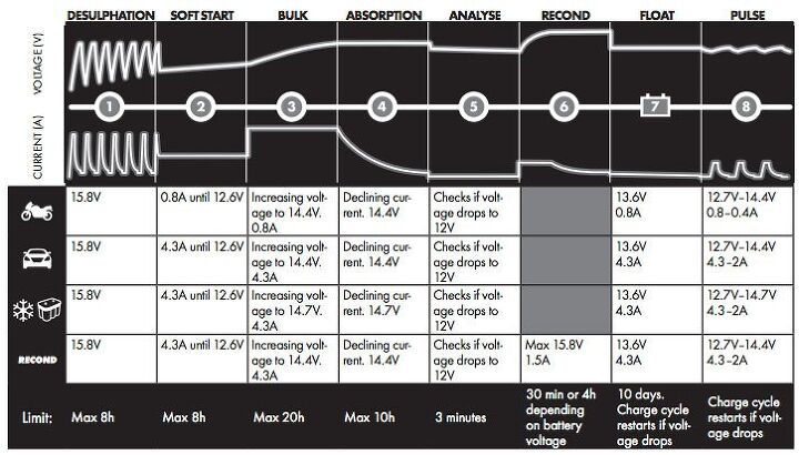
This is the graphic for the CTEK 4.3 (Quattro Pete posted for another charger).
Note that some of the text doesn't line up to the graphing - for example, presuming the graph is for regular car mode, the float current graphed is far less than the 4.3A in the text and the current in earlier stages. The graph's lower float current is confirmed by your testing.
I think there may be more decisions that the smart charger makes during stage 3 than just following the exact voltages and currents before transitioning to stage 4 as stated in the picture. As you both found, stage 3 ended without reaching 14.4V with a constant current. My experience is different. Sometimes it does, sometimes it doesn't. It usually does reach 14.4V but when it doesn't, the charger gets very hot and I sometimes turn it off and start again after a while.
I haven't made enough notes to see what the pattern is, but I suspect that more worn batteries are not accepting the higher voltage until later.
I do find that leaving the charger on for a day or two on float results in a noticeably stronger sounding and quicker start.
Edit: It's interesting that your absorption phase ended at about 10 hours which is the limit set by the charger. It would seem that if the CTEK doesn't complete stage 3 as per the graph, then stage 4 won't put enough charge into a more heavily depleted battery to fully charge it. Therefore, in such instances, leaving it on float would make a difference, as would charging it a second time.
Last edited:
I'm pretty sure all those amperages listed in the graph are what the charger will limit the current to in that mode, not a constant current set point.
Doesn't quite explain the flat line for stage 2 though, I'd guess the graph was originally made for a higher current charger that limited current in stage 2 vs stage 3.
Doesn't quite explain the flat line for stage 2 though, I'd guess the graph was originally made for a higher current charger that limited current in stage 2 vs stage 3.
My CTEK 7002 puts out 14.4 volt on standard setting, and 14.7V on AGM setting (at 77F), as in the chart above.
This is the graphic for the CTEK 4.3 (Quattro Pete posted for another charger).
My 20A Pro-Logix charger does the opposite: 14.7V on standard setting and 14.4V on AGM setting.
I tested the Noco Genius 1 on its AGM setting.
It is a 1 amp charger/maintainer
1 amp is applied until 13.7v, at which point the red pulsing light, starts pulsing green instead.
0.5amps is then applied until ~13.85v is reached
0.2 amps is then applied until voltage reaches 14.70v, at which point it shuts off and light stays a solid green.
When voltage falls to 12.69 it restarts, applying 0.2 amps until voltage rises to 14.1v, at which point it shuts off until voltage drops to 12.69v.
I was not monitoring closely at this stage, but once it hit 12.69v it started again with 0.2 amps output and once the voltage rose somewhere above 13.79 it shut off again at which point I stopped monitoring it completely. 12 hours later battery voltage was still over 13 and no amperage was flowing from charger.
I was using an LED light of adjustable amperage/brightness to drag down battery voltage more quicky as the small AGM battery will retain 13+ volts for days off he charger otherwise.
It could certainly behave a bit differently on a larger more discharged battery, when low amps take much longer to raise battery voltage.
This was tested on a UB12180 at very close to full charge when I started. It is an 18 amp hour 35$ chinese AGM battery, 2.5 years old and still performing well.
I think it is an Ok maintainer/charger especially for ~25$, as long as one is not expecting a full charge quickly or trying to recharge a deeply discharged AGM.
Again it could behave differently on a larger more discharged battery, and likely behaves differently on the non agm setting.
I'll not be observing its algorithm in future tests.
I tested the Noco Genius 1 on its AGM setting.
It is a 1 amp charger/maintainer
1 amp is applied until 13.7v, at which point the red pulsing light, starts pulsing green instead.
0.5amps is then applied until ~13.85v is reached
0.2 amps is then applied until voltage reaches 14.70v, at which point it shuts off and light stays a solid green.
When voltage falls to 12.69 it restarts, applying 0.2 amps until voltage rises to 14.1v, at which point it shuts off until voltage drops to 12.69v.
I was not monitoring closely at this stage, but once it hit 12.69v it started again with 0.2 amps output and once the voltage rose somewhere above 13.79 it shut off again at which point I stopped monitoring it completely. 12 hours later battery voltage was still over 13 and no amperage was flowing from charger.
I was using an LED light of adjustable amperage/brightness to drag down battery voltage more quicky as the small AGM battery will retain 13+ volts for days off he charger otherwise.
It could certainly behave a bit differently on a larger more discharged battery, when low amps take much longer to raise battery voltage.
This was tested on a UB12180 at very close to full charge when I started. It is an 18 amp hour 35$ chinese AGM battery, 2.5 years old and still performing well.
I think it is an Ok maintainer/charger especially for ~25$, as long as one is not expecting a full charge quickly or trying to recharge a deeply discharged AGM.
Again it could behave differently on a larger more discharged battery, and likely behaves differently on the non agm setting.
I'll not be observing its algorithm in future tests.
Strange, that’s not consistent with my test reported on page 1.
Ill rerun this or the 1A unit on the standalone battery. My accord has a lot of parasitic draws That are those spikes downward. But it’s sure not 13.73V. Unless you’re testing at 100F or hotter, that’s not a cutout I’d expect...
Similar threads
- Replies
- 5
- Views
- 2K
- Replies
- 11
- Views
- 11K