After my successful (so far) extinguishing of the CEL due to a very persistent P0455 EVAP code, I decided to press on with the ABS light that had also been staring me in the face far too long.
Years ago, I split the case, and fixed numerous cold/poor soldered pin joints. That would do it for awhile, then the ABS light would remind me there was more to do. I worked on it again, the light would go off for about 6 months, then come back on. I knew my solder joints were good, so something else was amiss.
Pulling the module this time was GREATLY exacerbated by one E5 bolt with a stripped head. I cut a slot across it using a diamond wheel + Moto-tool combination, but it wouldn't budge! Broke 3 screwdriver tips. So I went back with a ball-end carbide tool, and just ground off the entire head. Royal PITA due to the nearly upside location. My back still hurts just thinking about it.....
Persistence paid off however, and this is what I found after splitting the case:
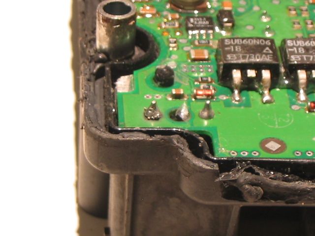
Bottom left hand corner, you see three pins in-a-line. Except the middle one is just a hole. So ignoring it, notice the difference between the left & right ones. Those funny little shiny bits and that dark circle under the left pin, stand out in contrast. Notice you don't see these characteristics on the right pin. I certainly didn't leave it that way last time.
So what's going on here?
Here's another angle:
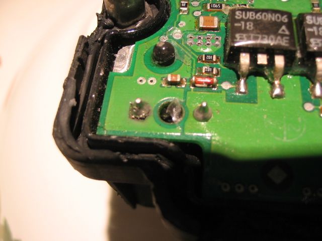
The problem is that the pad underneath this pin is far too small, resulting in the angle between the board & pin, being too high. IOW, ATE greatly undersized these pads for such a long, thick pin, responsible for carrying the current for the ABS system motor. The solution is to greatly enlarge the size of the pad, giving a better contact area, and lowering the angle.
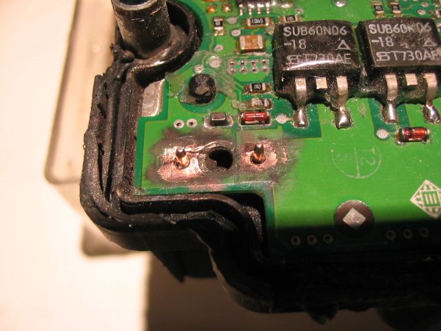
So out came the Moto-tool and a tiny chisel to scrape off the board etch-resist, to expose more copper underneath:
The next step was to take a hot well-tinned iron, and "wet" the raw copper to tin it. Then to heat the large pin enough so that solder would adhere to it and the pad and form a strong "cone" shape, to reinforce this joint:
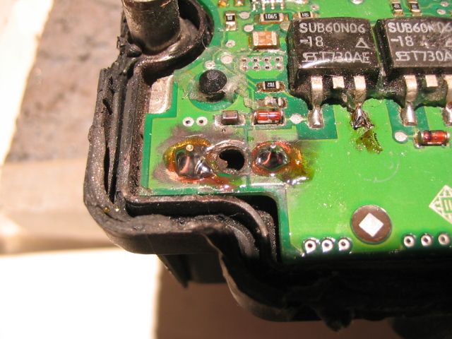
After it cooled, I cleaned the flux off with ethanol, glued the case back together, let it cure overnight and installed it this morning. Result? No more ABS light!!
Sure is nice having the sled's dashboard extinguished of idiot lights!! Hopefully, this fix will last longer than six months.
As a side-note, I originally hoped that Volvo + ATE would step up and recall these ABS controllers, as thousands upon thousands of them soon failed due to poor construction and hairline cracks. Unfortunately, they did not. So much for 'safety'.
Evidently, these ABS controller faults are not at all limited to Volvos, since other European manufacturers used ATE controllers as well.
Finally, it's interesting that while earning my EE degree from a major university, I never had to learn to solder! Yet over the past 30+ years, I've found numerous faults that were due to hairline solder cracks, cold soldered joints and here, undersized pads + poor soldered joints. When lead-free solder emerged, the problems were magnified as LF requires much higher heat in order to form a normal joint, much less to a large pin, carrying significant current, that controls a motor as critical as an ABS system motor.
Go figure.....
Years ago, I split the case, and fixed numerous cold/poor soldered pin joints. That would do it for awhile, then the ABS light would remind me there was more to do. I worked on it again, the light would go off for about 6 months, then come back on. I knew my solder joints were good, so something else was amiss.
Pulling the module this time was GREATLY exacerbated by one E5 bolt with a stripped head. I cut a slot across it using a diamond wheel + Moto-tool combination, but it wouldn't budge! Broke 3 screwdriver tips. So I went back with a ball-end carbide tool, and just ground off the entire head. Royal PITA due to the nearly upside location. My back still hurts just thinking about it.....
Persistence paid off however, and this is what I found after splitting the case:
Bottom left hand corner, you see three pins in-a-line. Except the middle one is just a hole. So ignoring it, notice the difference between the left & right ones. Those funny little shiny bits and that dark circle under the left pin, stand out in contrast. Notice you don't see these characteristics on the right pin. I certainly didn't leave it that way last time.
So what's going on here?
Here's another angle:
The problem is that the pad underneath this pin is far too small, resulting in the angle between the board & pin, being too high. IOW, ATE greatly undersized these pads for such a long, thick pin, responsible for carrying the current for the ABS system motor. The solution is to greatly enlarge the size of the pad, giving a better contact area, and lowering the angle.
So out came the Moto-tool and a tiny chisel to scrape off the board etch-resist, to expose more copper underneath:
The next step was to take a hot well-tinned iron, and "wet" the raw copper to tin it. Then to heat the large pin enough so that solder would adhere to it and the pad and form a strong "cone" shape, to reinforce this joint:
After it cooled, I cleaned the flux off with ethanol, glued the case back together, let it cure overnight and installed it this morning. Result? No more ABS light!!
Sure is nice having the sled's dashboard extinguished of idiot lights!! Hopefully, this fix will last longer than six months.
As a side-note, I originally hoped that Volvo + ATE would step up and recall these ABS controllers, as thousands upon thousands of them soon failed due to poor construction and hairline cracks. Unfortunately, they did not. So much for 'safety'.
Evidently, these ABS controller faults are not at all limited to Volvos, since other European manufacturers used ATE controllers as well.
Finally, it's interesting that while earning my EE degree from a major university, I never had to learn to solder! Yet over the past 30+ years, I've found numerous faults that were due to hairline solder cracks, cold soldered joints and here, undersized pads + poor soldered joints. When lead-free solder emerged, the problems were magnified as LF requires much higher heat in order to form a normal joint, much less to a large pin, carrying significant current, that controls a motor as critical as an ABS system motor.
Go figure.....
