I'm trying to determine if I have actual high pressure or if my transducer is faulty and why there is so much noise in my readings. I'm not sure if what I am seeing is accurate or not. To recap the setup:
2000 Fbody, 2005 core, Jakes D3 Plus, Machined EPC block off plug, line to lube in pump drilled .093, OE Boost Valve (new) 24202644, OE Boost Sleeve (new) 24202645, OE pressure regulator valve (new) 8680547, OE washer (used), OE isolator spring (used), OE pressure regulator spring (used), Sonnax 34200-05K o-ringed end plug.
Additional details:
-The PR valve assembly in the bore is all installed in the correct orientation
-The boost valve moves nicely inside the sleeve
-The PR valve moves nicely inside the bore
-Reverse servo cover was sanded, new gasket used, air check on the case for that reverse servo was good
-Dual fed directs
-The reverse feed is not plugged in the case, nor on the center support as jakes D3 valve body handles dual feeding a different way
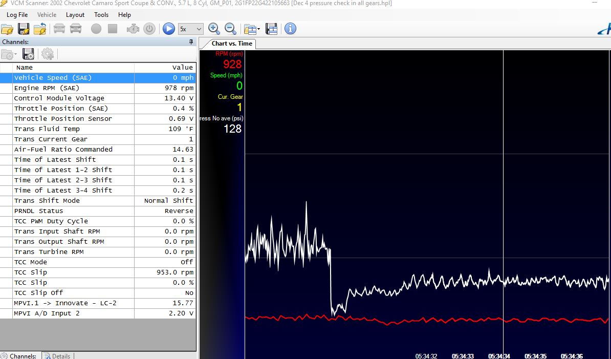
-Reverse boost is killed in this iteration of Jakes D3 valve body which means pressures in forward should be the same as in reverse, so shouldn't see 280-300 in R
-I didn't use a spring rated for higher pressure because I wanted to see what would happen with a stock assembly in the pump and get a baseline
-All pressures in the images below are with a calibrated dip stick marked at full hot, 1/4 above the pan rail
-Trans temps never got over 126F, even with a wot pull. It was 40F outside and I'm running a Trucool 40k with rad bypassed. Typically car isn't ran in these temps.
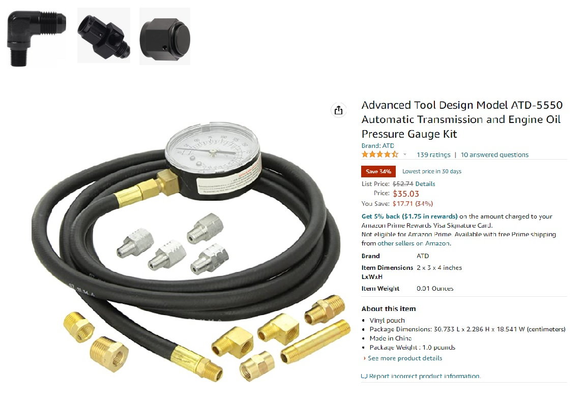
-The pressure was logged using a low dollar motorsports pressure transducer seen in the first link below
-HP Tuners MPVI 1 was used the tuning software used to log
-All the voltages and resistances as they pertain to correctly logging with a transducer were verified correct, all transfer math functions in the software are correct
-The transducer is installed using the fittings seen in the image below, and a 6AN cap is used for manual pressure gauge hook up.
-I can log digitally and manually at the same time. When I did this simultaneously during the initial test runs, the numbers were close between digital and manual.
-For the pictures and the logs below, I didn't have the manual pressure gauge hooked up as it's a PITA to get to with the trans installed and I figured digital was good enough, since the numbers were close.
-All the circuits on the valve body and the pump were vacuum checked and the vacuum numbers inboard and outboard for each valve were all in spec prior to install. -All case holes were shot with air to verify correct clutch engagement in each stack.
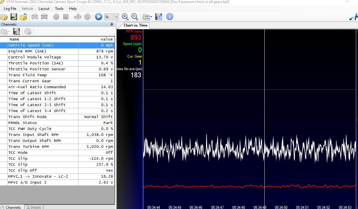
-The numbers at "warm idle" with blocked EPC seem very high despite the trans temp of 120-130F. I'm seeing 200 PSI once the trans is "warmed up" in park and it spikes much higher when reving at 2000 rpm or so.
- The trans shifts perfect, and it drives perfect. Lockup is working as it should right where I commanded it. Car pulls HARD.
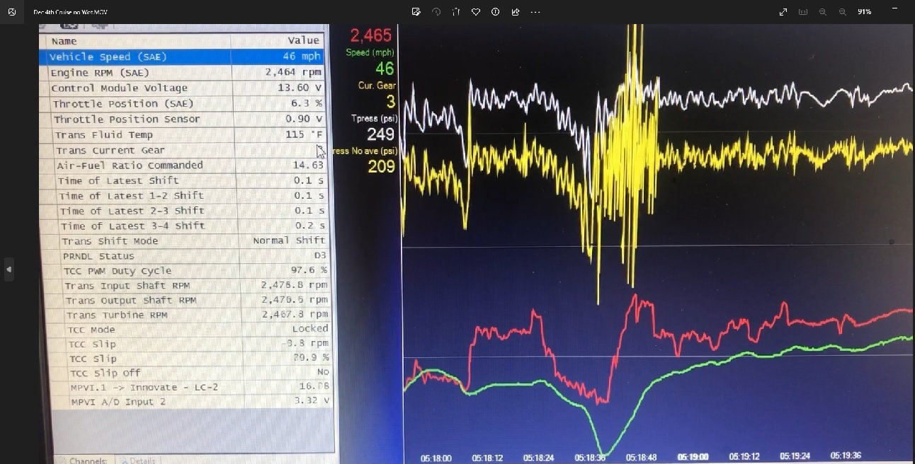
-Pressure shows a steady 200-210 PSI while locked in 4th gear, that seems to be far less noise than any other part of the run.
-Dropped the pan, no metal, fluid looks mint.
-With pan dropped, pulled the parts out of the PR pump bore assembly and they all look fine and nothing is being hung up/stuck.
-I'm using this: https://lowdoller-motorsports.com/collections/pressure-sensors/products/0-300-psi-5v-pressure-sensor
These links are videos of the logs one with a wot pull, one checking pressures in the various gears with the trans warmed up to 116 or so, and one just cruising around and no wot pull. You can see what gear is commanded on the PRNDL (for some reason neutral shows as park), and notice the RPM and MPH along with the pressure increases.
Ignore the white line in the videos, the yellow line without the average function is 30-40 PSI lower than the white line.
If the files won't play right from the link, they can be downloaded and then they should work.
The white line in the images however has the correct parameters entered into the software.
If the media won't download, try replacing "dot" with "."
https://drive.google dot com/file/d/1t472g_yUxM0tKxQY362bZDetqxtXWNBd/view?usp=share_link
https://drive.google dot com/file/d/12r-W9zg9F_CLqYVpPtRu7db-l2K1ndHK/view?usp=share_link
https://drive.google dot com/file/d/19ke_jQ6e6qL641hCedPoehC3uZfND-TC/view?usp=share_link
My questions are:
1. Should I try a different transducer and see if that fixes the noise that I'm seeing in the readings?
2. I looked at a log using a 100ms filter and the "average" function but it didn't seem to help with the noise
3. Would you say that there is a leak in the forward circuit somewhere? I don't see the o-ring end plug in the PR bore having come out but maybe it's possible?
4. Based on the logs, and trends seen in the various gear selections at idle and at higher RPM along with the log files, where would the leak be located?
At this point, I don't even know if the transducer is giving accurate pressure readings.
Plan is to get a new transducer and log it again once it warms up after the winter with the mechanical gauge hooked up at the same time. The mechanical gauge I have that initially looked to be the same numbers as the transducer is below. If there is in fact a high pressure issue, I don't want to be running it for risk of blowing the case lugs.
Neutral Idle
Reverse
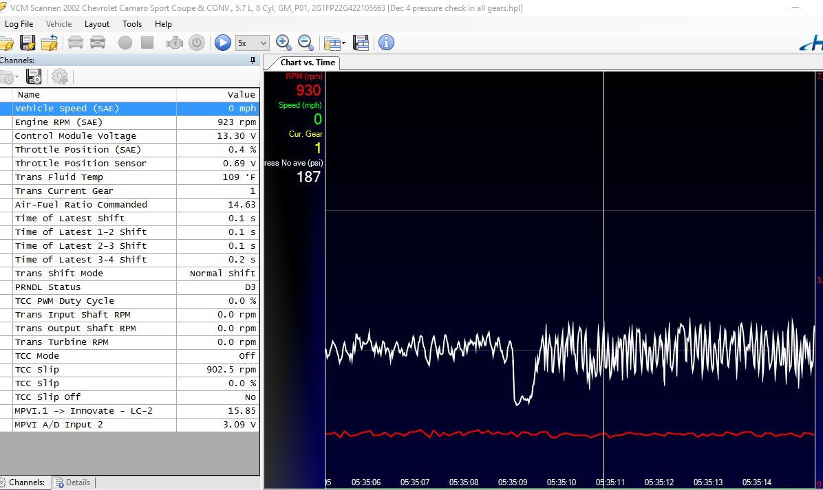
D3 and D4 idle - (log file in link above shows where transition occurred)
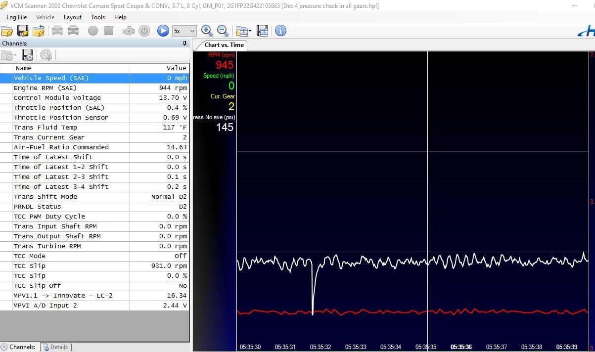
D2 idle
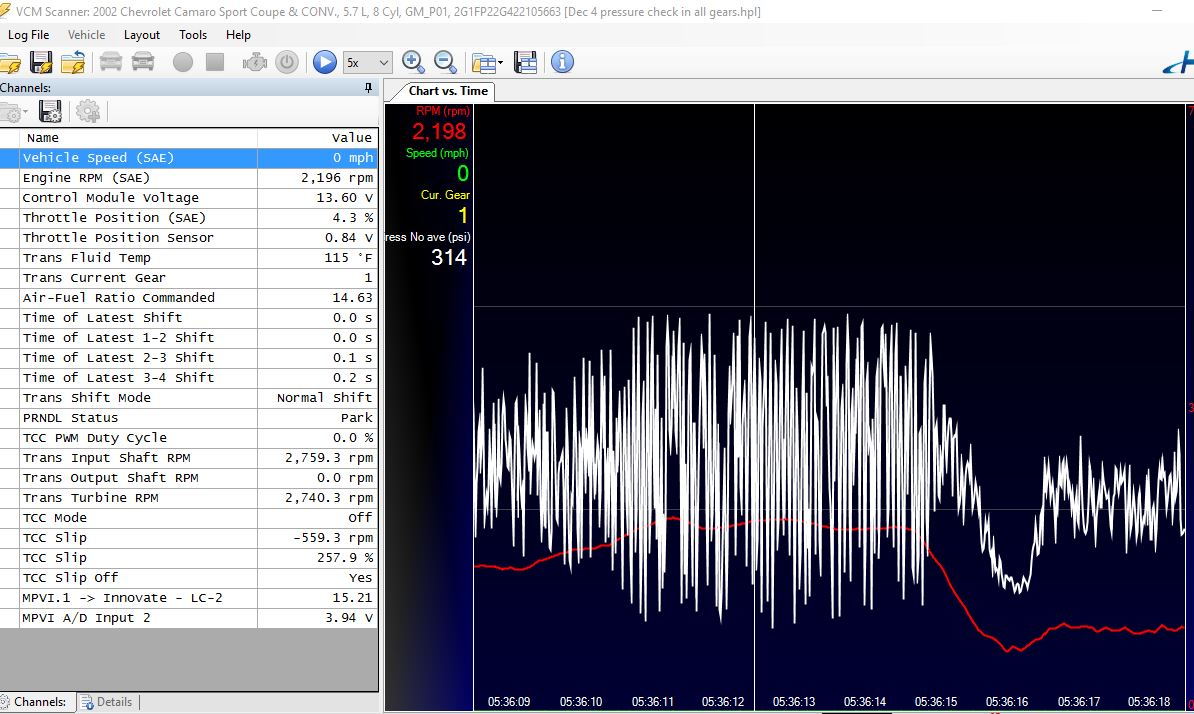
Park higher RPM
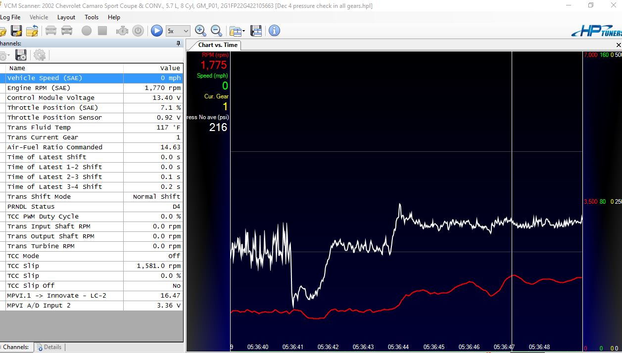
D4 higher RPM
2000 Fbody, 2005 core, Jakes D3 Plus, Machined EPC block off plug, line to lube in pump drilled .093, OE Boost Valve (new) 24202644, OE Boost Sleeve (new) 24202645, OE pressure regulator valve (new) 8680547, OE washer (used), OE isolator spring (used), OE pressure regulator spring (used), Sonnax 34200-05K o-ringed end plug.
Additional details:
-The PR valve assembly in the bore is all installed in the correct orientation
-The boost valve moves nicely inside the sleeve
-The PR valve moves nicely inside the bore
-Reverse servo cover was sanded, new gasket used, air check on the case for that reverse servo was good
-Dual fed directs
-The reverse feed is not plugged in the case, nor on the center support as jakes D3 valve body handles dual feeding a different way
-Reverse boost is killed in this iteration of Jakes D3 valve body which means pressures in forward should be the same as in reverse, so shouldn't see 280-300 in R
-I didn't use a spring rated for higher pressure because I wanted to see what would happen with a stock assembly in the pump and get a baseline
-All pressures in the images below are with a calibrated dip stick marked at full hot, 1/4 above the pan rail
-Trans temps never got over 126F, even with a wot pull. It was 40F outside and I'm running a Trucool 40k with rad bypassed. Typically car isn't ran in these temps.
-The pressure was logged using a low dollar motorsports pressure transducer seen in the first link below
-HP Tuners MPVI 1 was used the tuning software used to log
-All the voltages and resistances as they pertain to correctly logging with a transducer were verified correct, all transfer math functions in the software are correct
-The transducer is installed using the fittings seen in the image below, and a 6AN cap is used for manual pressure gauge hook up.
-I can log digitally and manually at the same time. When I did this simultaneously during the initial test runs, the numbers were close between digital and manual.
-For the pictures and the logs below, I didn't have the manual pressure gauge hooked up as it's a PITA to get to with the trans installed and I figured digital was good enough, since the numbers were close.
-All the circuits on the valve body and the pump were vacuum checked and the vacuum numbers inboard and outboard for each valve were all in spec prior to install. -All case holes were shot with air to verify correct clutch engagement in each stack.
-The numbers at "warm idle" with blocked EPC seem very high despite the trans temp of 120-130F. I'm seeing 200 PSI once the trans is "warmed up" in park and it spikes much higher when reving at 2000 rpm or so.
- The trans shifts perfect, and it drives perfect. Lockup is working as it should right where I commanded it. Car pulls HARD.
-Pressure shows a steady 200-210 PSI while locked in 4th gear, that seems to be far less noise than any other part of the run.
-Dropped the pan, no metal, fluid looks mint.
-With pan dropped, pulled the parts out of the PR pump bore assembly and they all look fine and nothing is being hung up/stuck.
-I'm using this: https://lowdoller-motorsports.com/collections/pressure-sensors/products/0-300-psi-5v-pressure-sensor
These links are videos of the logs one with a wot pull, one checking pressures in the various gears with the trans warmed up to 116 or so, and one just cruising around and no wot pull. You can see what gear is commanded on the PRNDL (for some reason neutral shows as park), and notice the RPM and MPH along with the pressure increases.
Ignore the white line in the videos, the yellow line without the average function is 30-40 PSI lower than the white line.
If the files won't play right from the link, they can be downloaded and then they should work.
The white line in the images however has the correct parameters entered into the software.
If the media won't download, try replacing "dot" with "."
https://drive.google dot com/file/d/1t472g_yUxM0tKxQY362bZDetqxtXWNBd/view?usp=share_link
https://drive.google dot com/file/d/12r-W9zg9F_CLqYVpPtRu7db-l2K1ndHK/view?usp=share_link
https://drive.google dot com/file/d/19ke_jQ6e6qL641hCedPoehC3uZfND-TC/view?usp=share_link
My questions are:
1. Should I try a different transducer and see if that fixes the noise that I'm seeing in the readings?
2. I looked at a log using a 100ms filter and the "average" function but it didn't seem to help with the noise
3. Would you say that there is a leak in the forward circuit somewhere? I don't see the o-ring end plug in the PR bore having come out but maybe it's possible?
4. Based on the logs, and trends seen in the various gear selections at idle and at higher RPM along with the log files, where would the leak be located?
At this point, I don't even know if the transducer is giving accurate pressure readings.
Plan is to get a new transducer and log it again once it warms up after the winter with the mechanical gauge hooked up at the same time. The mechanical gauge I have that initially looked to be the same numbers as the transducer is below. If there is in fact a high pressure issue, I don't want to be running it for risk of blowing the case lugs.
Neutral Idle
Reverse
D3 and D4 idle - (log file in link above shows where transition occurred)
D2 idle
Park higher RPM
D4 higher RPM
Last edited: