Newly-rebuilt 4L60E lost 3rd gear within 20 miles, sigh...

The band looks good, I'll post a pic of the drum tomorrow. It has a little discoloration (new drum and wide band).
Also will take a closer look at the other frictions.

The sealing rings look good, new teflon ones.

No rust in the stator support. Some other bits were rusty, but we replaced them all.

Pressure switch seals are good, its new as well.

I'll give pressure testing the 3rd Accumulator and let you know.
 
Couldnt get to much more than photos today, slight family issue.

Pic of the band and drum. I'm thinking they got hot.

band and drum.jpg
 
Last edited by a moderator:
The 3 pistons in the input drum look great, seals are supple and not nicked or torn.

Pressure tested the 3rd Accumulator checkball capsule, no fluid at all going past it. Decent amount coming out of the Band / Drum lube hole.
 
Ive ordered the bits and bobs to make a vacuum test stand, hopefully i'll be able to vacuum test the pump and valve body this Saturday.
 
Also, got the rest of the trans torn down, and the low/reverse clutch frictions are toasted as well.

Hmm...
 
I'm going think on that one, LR Clutch burn up is unusual on a fresh unit......How did you verify the LR clearance during assembly?
Couldn't find my original chicken-scratching notes, but my original thread had the info - thank goodness for internet build threads!

Measured the Low-Reverse clutch pack according to ATRA book page 145, pictured below

Low Rev Clutch: ATSG book says 1.200-1.240", ATRA book maths out to 1.107-1.214, TransTec instruction sheet says 1.15 to 1.18

* Low/Reverse Clutch: 1.185" overall height with wave plate, OEM/BW frictions, new turbulator steels, and OEM selective plate.

Don't know if it matters, but the frictions on the top and bottom of the stack weren't that bad - but the middle ones were scorched and crumbly, and parts of the steels have been turned blue. (yow!)

ATRA Book Low Reverse Clutch Specs.jpg
 
Last edited by a moderator:
Always verify that you have clearance through the little window in the Case with a Awl or Pocket Flat Blade (Red Arrow).....The Wave should move at least .060", But up to .100" is fine. I realize there's no way to measure with absolute accuracy, But soon as I install the Center Support Snap Ring. I flip the case horizonal & check that the Wave Plate moves a good amount with a pocket screwdriver.

C4amibN.jpg
 
  • Like
Reactions: GON
Will do when we assemble, great tip!

Vacuum tested the pump and valve body this afternoon, the lowest reading was 19 inches at the 4-3 sequence and 3-4 relay valves, most were 20-21 inches.

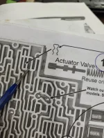
EXCEPT - the 'upper' passage of the Forward Abuse Valve (upper blue arrow) wouldnt hold ANY vacuum, even with the passage to the pressure switch manifold (lower blue arrow) plugged. Is there another passage that I need to plug or is it that bad?

Edit: I also need to vacuum test the end plugs and 3-2 Control Valve, after removing the spring so the valve can go to that end of the bore.

1701746787734.jpeg
 
You should replace both bore plugs. But is this the cause for a 20 mile burn up?....I HIGHLY doubt it!

I thank Sonnax for their contributions to the industry, But you can buy a Sonnax Valve Body that doesn't pass there own pass/fail criteria when it comes to vacuum testing.
 
Ive got oringed bore plugs on the way.

Forward or Reverse Abuse Bore Plugs?

Also, when vacuum testing, should the valves be wet or dry? I tested mine just as it came off the case (wet) which may account for the high vacuum readings.
 
Found one thing that i'm pretty sure I did wrong... @clinebarger , what do you think?

When reassembling the valve body, I noticed that the retaining clip for the plug behind the AFL valve / spring goes into the 4th "slot" in from the edge, and that to get it in (with the additional TransGo spring) took a LOT more effort than I remembered.

I'm pretty sure that I had the retaining clip installed into the 3rd slot. And if I'm reading the books right, that would result in lower AFL circuit pressure, which apparently leads to burned clutches.
 

Attachments

  • 20231218_182710.jpg
    20231218_182710.jpg
    155 KB · Views: 19
  • 20231218_182650.jpg
    20231218_182650.jpg
    172.8 KB · Views: 20
Yup, that wasn't it - in fact the PC Solenoid won't seat unless the AFL bore plug is in all the way. Dangit, I still haven't found anything glaringly wrong...

Did a proper vacuum test today, clean and dry valve body and properly calibrated test stand.

TCC Regulator Valve (outboard) = 16.6"
TCC Regulator Valve (inboard) = 21.5"
Actuator Feed Limit Valve = 20"
Accumulator Valve and Sleeve = 21"
2-3 Shuttle Valve (outboard)= 22"
2-3 Shuttle Valve (inboard) = 20"
2-3 Shift Valve = 16.5"
1-2 Shift Valve (outboard) = 23"
1-2 Shift Valve (inboard) = 21.5"
Low Overrun Valve = 18"
Forward Abuse Bore Plug = 20"
Forward Abuse Valve (outboard) = 16.5
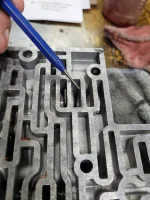
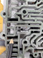
Forward Abuse Valve (inboard) = 5" See note and pic below
Reverse Abuse Valve = 20"
3-2 Control Valve (with spring removed and valve bottomed in bore): Outboard = 22", Inboard = 24"
Reverse Abuse Bore Plug = 23"
3-4 Shift Valve (outboard) = 20"
3-4 Shift Valve (inboard) = 22"
4-3 Sequence Valve and 3-4 Relay Valves from Outboard to Inboard: 18", 20", 20.5", 22"
End Plugs (new with o-rings) all 25"

Odd thing about this valve body is that when testing the Forward Abuse Valve inboard spot, that slot connects to the Manual Shift Bores, which are all open to atmosphere - all those passages under the pencil shown. So Unless somebody has an idea, I'm unable to confirm that one Valve.
 

Attachments

  • Reverse Abuse Passage.jpg
    Reverse Abuse Passage.jpg
    209.9 KB · Views: 9
Yup, that wasn't it - in fact the PC Solenoid won't seat unless the AFL bore plug is in all the way. Dangit, I still haven't found anything glaringly wrong...

Did a proper vacuum test today, clean and dry valve body and properly calibrated test stand.

TCC Regulator Valve (outboard) = 16.6"
TCC Regulator Valve (inboard) = 21.5"
Actuator Feed Limit Valve = 20"
Accumulator Valve and Sleeve = 21"
2-3 Shuttle Valve (outboard)= 22"
2-3 Shuttle Valve (inboard) = 20"
2-3 Shift Valve = 16.5"
1-2 Shift Valve (outboard) = 23"
1-2 Shift Valve (inboard) = 21.5"
Low Overrun Valve = 18"
Forward Abuse Bore Plug = 20"
Forward Abuse Valve (outboard) = 16.5
Forward Abuse Valve (inboard) = 5" See note and pic below
Reverse Abuse Valve = 20"
3-2 Control Valve (with spring removed and valve bottomed in bore): Outboard = 22", Inboard = 24"
Reverse Abuse Bore Plug = 23"
3-4 Shift Valve (outboard) = 20"
3-4 Shift Valve (inboard) = 22"
4-3 Sequence Valve and 3-4 Relay Valves from Outboard to Inboard: 18", 20", 20.5", 22"
End Plugs (new with o-rings) all 25"

Odd thing about this valve body is that when testing the Forward Abuse Valve inboard spot, that slot connects to the Manual Shift Bores, which are all open to atmosphere - all those passages under the pencil shown. So Unless somebody has an idea, I'm unable to confirm that one Valve.
Well????
 
Back
Top