Parallel Battery Current Flow Test

Status
Not open for further replies.

JHZR2

Staff member
Joined
Dec 14, 2002
Messages
52,802
Location
New Jersey
My 81 240D is in a garage without electricity, and has been sitting since the summer. I out it away hot and with a full battery, but I was worried about self discharge. Given the road salt, I didn't want to drive it around (though it would be good to turn on to cycle the AC).

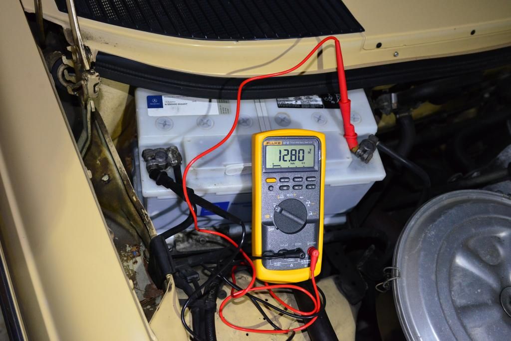
I went to check the battery and found it to be a respectable 12.18V. Granted it was about 17F out. Per this site, that means I should be around 75% SOC. Not bad at all!

http://www.buchanan1.net/lead_acid.html

So I took a group 29 deep cycle battery that I keep around as a spare off of the float charge and brought it to the car. I wanted to SE how the current flow would behave and how the starter battery in the car would take it.

The car battery is an OE MB group 49, the other is a 29 deep cycle with 122Ah at 1A.

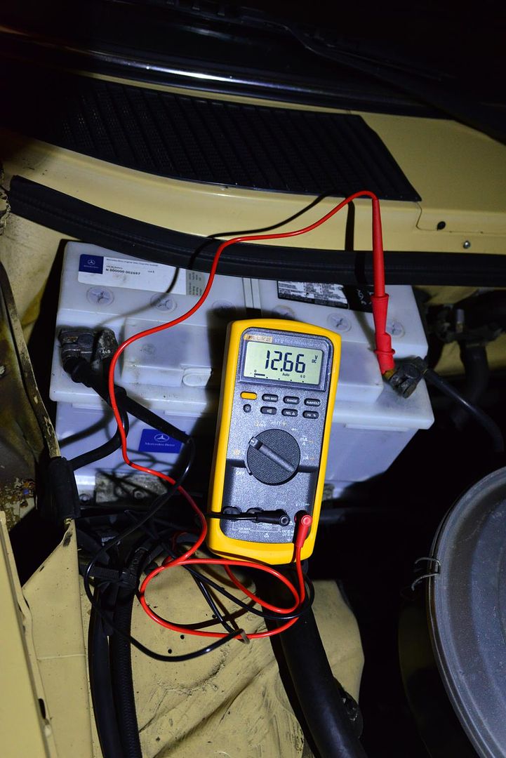
Here are the results:


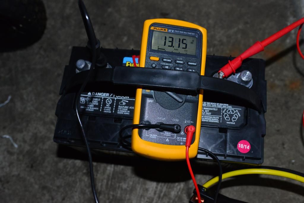
The voltage on the deep cycle group 29 battery was about 13.18V before connecting, and after the current flowed ~13.15V - it really only removed what, a few Amp-minutes from a 122A-h deep cycle battery.

FX1_1019_zpsyavx5jwp.jpg


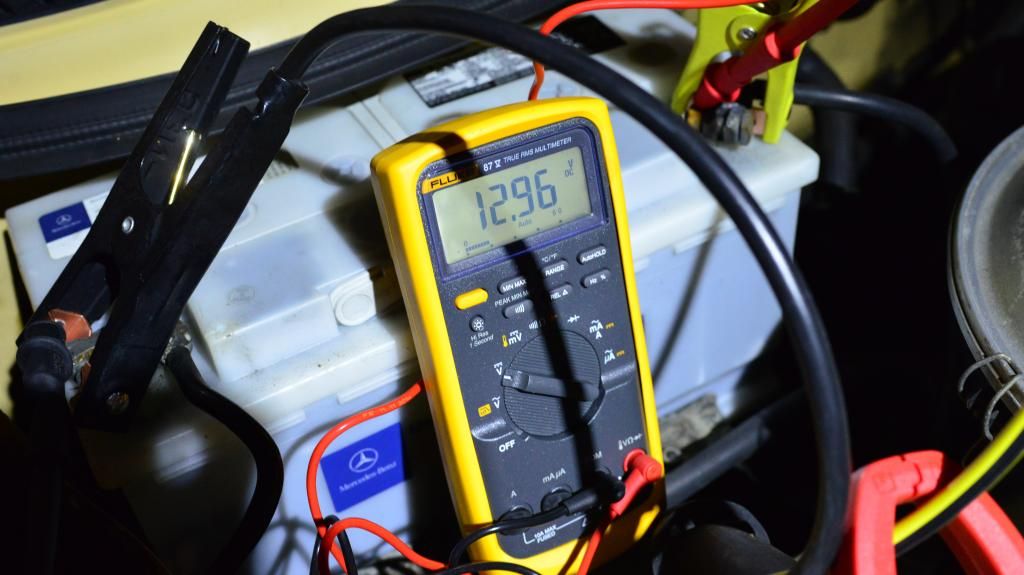
Then the battery on the car dropped back, as expected...

FX1_1017_zpseu7uj9se.jpg


FX1_1020_zpsjwnw8tlx.jpg


FX1_1021_zpsok65aeih.jpg


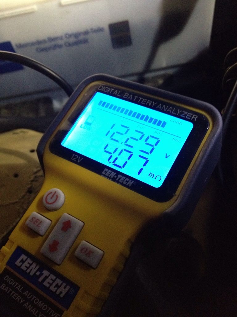
The jumper cables used had resistance of less than 0.2 Ohm, which is about all my meter can show.

Frankly I was rather surprised that it peaked at only a bit over 4A, and that it decayed so quick. After all, the source impedance should be really low as a fully charged lead acid battery. The load impedance is the combination of the say 0.2 ohm worst case plus the impedance of the battery. I didnt have my analyzer with me to try, but I'd guess it would still be a good deal less than the impedance of the cables.

I haven't done the math, but the numbers show what they show... For a voltage delta of 1V, only 4A flows max, and quickly decreases as the recipient battery's voltage increases. How it increases so fast is also behind me. While frozen electrolyte is a potential, given the SOC vs voltage at various temperatures given above tells me that SOC was high enough for this to not be the case.

I was hoping to see more and sustained current flow, but didn't. I need to account for all the impedances to accurately reflect the situation.
 
There is a difference between the voltage present at the terminals of an unloaded battery and the voltage necessary to actually charge the battery. For a lead/acid 6 cell battery, you need about 13.7 VDC to charge. Measuring the system voltage with engine running you should see this voltage.

The current/voltage relationship near the transition from charge to discharge is nonlinear. Very little current will flow between 12.5 and 13.5 VDC.

If you want to charge the car battery, use a trickle charger (or conventional charger) and float the terminals at 13.7 .

Watch for corrosion in the fender well below the battery; small gravel will accumulate down there and hold moisture and any battery acid that gets washed down there.
 
My automatic battery charger behaves about the same, except that it pushes the voltage to about 14.8V. On a fairly healthy battery the current starts at about 4-6A and quickly drops from there.

Having two batteries connected, with no external power source, I can see how they would equalize fairly quickly. If you added a small load to the low battery, like a small 12V bulb, you would see that the 4A current flow would remain for much longer.
In fact this is the way to "trick" most of the automatic type trickle chargers, as they usually shut off too early and don't charge the battery to full 100%.
 
I'll caveat that I do battery work and engineering in real life.

The real curiosity here stems back to my desire to parallel two dissimilar batteries, with different impedances and different SOCs to keep up against minor draws in a garage with no electric and no good sun for solar. I'm not running extension cords, so I'm looking for a serviceable capability.

I was interested in seeing about inrush given the voltage delta.

Practically speaking in parallel batteries we see fairly drastic behaviors under load and charge even with impedance and SOC matched batteries.

If you were actually trying to charge, the correct voltage would be the Voc+I*R so the open circuit voltage times the desired current times the battery impedance. An appropriate charge would continue at constant current until a maximum voltage was reached which pertains to the onset of excessive gassing and/or other damage (eg oxidation). At that point, constant voltage is maintained until the current drops to a defined level.

That's all a different scenario than I was looking at here.
 
Originally Posted By: Rand
I'm surprised you have a garage without electricity.


I have an extra garage that doesn't. There are plenty of buildings in existence without electricity. Nothing to it.
 
My idea is instead of carrying a battery to the MB, carry the MB battery to a charger. Similar amount of work that still accomplishes the mission.
wink.gif


Glad I could help.
 
Last edited:
Nope, don't want to have to unbolt and remove from the cowl area, nor stress the battery connections on the car.

Plus I typically install an SAE connectot for fast connection of a charger. So one of the determinations that made me want to do this was to see if the parallel batteries would exceed those conductors' ampacity.

And I like having a spare DC battery at home since the phone and internet system requires a battery backup.
 
Thanks for the post, very interesting! Also useful to know the interaction when a jump box is initially connected to a dead car.

Any windows in the garage that you could put a solar panel in?

Was the Deep Cycle battery at rest when it measured 13.18V? It seems high even if coming from indoors, but I'm assuming it must have been at rest if it only dropped ~.03V during the test. Maybe you could do this same test in the spring time right before you try start it up. I'd be even more curious to see the current when the MB battery is at an even lower SOC.

Also, nice job keeping your meter pristine, my Flukes aren't nearly as yellow anymore...
 
Originally Posted By: EdwardC
Thanks for the post, very interesting! Also useful to know the interaction when a jump box is initially connected to a dead car.

Any windows in the garage that you could put a solar panel in?

Was the Deep Cycle battery at rest when it measured 13.18V? It seems high even if coming from indoors, but I'm assuming it must have been at rest if it only dropped ~.03V during the test. Maybe you could do this same test in the spring time right before you try start it up. I'd be even more curious to see the current when the MB battery is at an even lower SOC.

Also, nice job keeping your meter pristine, my Flukes aren't nearly as yellow anymore...


Thanks! I keep them in plastic bags and try to keep them looking good (indoor kit). I have a 179 that is FAR dirtier, but was out for service. It came back and Fluke did a good job of cleaning it when they worked on it.

The most interesting thing is that the SOC didn't drop much on the MB group 49. They are very good batteries, known to be so. And the only draw on the entire car is a quartz clock, the car is entirely mechanical.

The 29 DC was just put into service by me about a month ago. It has been sitting on a float charger, and I pulled it and didn't connect anything to it. So it is reasonable, IMO that the surface charge remained. Im surprised though that it has enough double layer capacitance to it to still hold a decent surface charge after dumping say, 2A on average for a few minutes...

Still, figure
The Marine DC battery may also be fairly high impedance compared to SLI batteries, which would have slowed the current flow as well. Do it with a new Group 49 and the results may differ...

All the same, there just isn't a ton of overpotential to drive a large amount of current flow. I did expect to see a higher initial inrush though...
 
Perhaps a scope might have shown a higher initial current, lasting only for a fraction of a second and hence not picked up by a multimeter.

The battery voltage rises as soon as it begins accepting a charge. My best guess is that the battery voltage went up from 12.18v in that fraction of a second and that is why your meter reading showed max 4 amps.

I expect that if you monitor both battery voltage and current on a scope, everything would work exactly as per Ohm's law and that current = ( instantaneous 29 battery voltage - instantaneous MB battery voltage) / cable and connection resistance.
 
i would argue because the batteries provide power via chemical reaction that it would not work out exactly per ohms law V=IR.
As lead-acid car batteries charge and discharge, their internal resistance becomes variable.
 
... not saying ohm's law is not true but rather you can't observe it mathematically easily because of the varying resistance.
what you need is 3 or more multimeters, one on each battery measuring voltage between + and - terminal, and one or more in series measuring current flow between batteries.
if you were able to record all the voltages and currents at a given instant then i think you would be able to see numbers working out to ohms law under a steady state condition and back out the internal resistance of each battery.
and because the battery is chemical reaction, it's just not simple resistance it's really impedance and a lot more math
http://batteryuniversity.com/learn/article/how_to_measure_internal_resistance
 
ESR inside a battery is found by an axis crossing when applying a sweep of various frequency pulses. It is a very standard process.

There are other means of figuring it out, including some cheap lead acid battery testers which apply some algorithm. The algorithm on the cen-tech indicated about 8mOhm on the donor battery, didn't test the other, but I did find the value a year or two ago.

6CE465B8-B64C-4FE7-A30B-A5B207D71FF8-5443-0000092EBE847316_zps7739bcc1.jpg


If this is correct, it means that the source impedance is double the load impedance. That may or may not be correct. I checked the donor deep cycle battery in colder weather (battery impedance is temperature dependent), and I used the marine cranking amps value the nameplate provided, meaning that it probably was basing the calculation on too high a cranking amp capability.
 
Status
Not open for further replies.
Back
Top