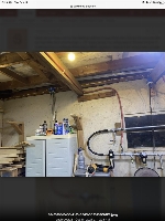
Nearly finished my compressor install, please critique!

Joined
Aug 24, 2021
Messages
39
Hey all, just nearly finished the install of my air system with advice of those on this forum. After completing everything I pressurized it and cut off the air supply from the tank. I had the regulator set at 100 psi and after about 4 hours I saw that it lowered to 30 psi. I went around with soapy water to find any small leaks. I found 2, fixed them and pressurized again. Cut of the tank supply, regulator at 100 psi and after about 14 hours it was down to about 85 psi. I checked for leaks and couldn’t find anything, figured it was so light that it isn’t a big deal.

So I’ll explain the setup. The compressor is a Quincy 80 gallon with 7.5 HP Baldor single phase motor and an inter cooler/after cooler.
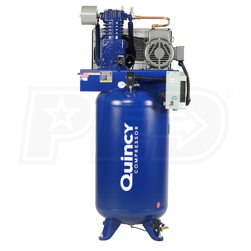

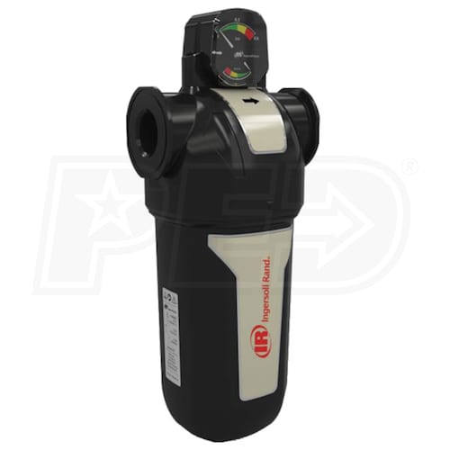
Out of the compressor there is a ball valve that is hooked to a 7 foot long 3/4” hydraulic hose to isolate vibration from the wall. It then goes through a 10 foot length of 3/4” steel pipe. There is then a drop down with a ball valve so that I can evacuate any water that might be in the system. It continues through another 3 foot length of hydraulic hose to turn a 180. It goes into a Ingersoll Rand FA75IH filter.

9C25268B-74BC-44A7-8A49-A59C0681E5BE.jpeg

47A9EA2C-0BA8-4CD1-868D-085DC9AC42B9.jpeg

CB7B52F2-A46D-4A97-AFFA-CED2C4D02011.jpeg


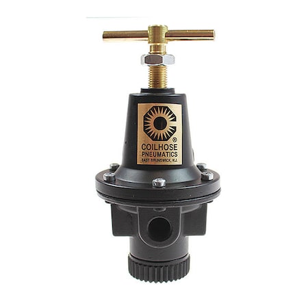
I was told that I should have at least 10 feet of piping between the compressor and the first filter. With the hydraulic hoses and the steel pipe I have just over 20 feet. After that filter I have a 1/2” compressor hose running through a ball valve to my blasting cabinet. I wanted full tank pressure to run to the cabinet (150 psi) and then have a regulator at the cabinet. After the run there is a standard high flow hose fitting, just so if I want to I can use 150 psi through the air gun to blow out the dust or to fill my tires. It then goes into a Coilhose Pneumatics 8806 regulator

0CAD6945-7CBE-4858-98F3-22D83751C280.jpeg


This takes the pressure of 150 psi down to a hair over 90. After the regulator I step the pipe down from 3/4” to 1/2”. I have another drop down with all valve for any water. Of course I’ve had zero water from any of the drop downs. It then goes into a Motor Guard M-60 submicronic compressed air filter. It has the same rating as the IR filter I’m using, just at a lower PSI rating.
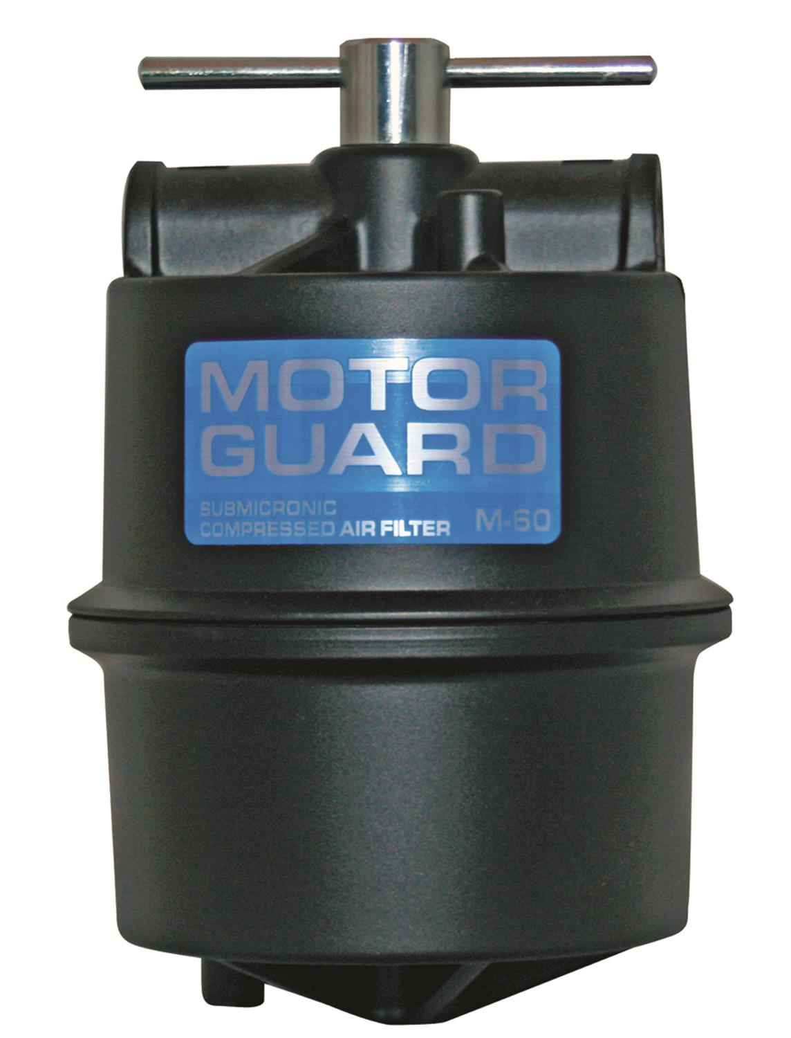

D3A3FDDA-E69C-4687-BC10-152F52650D0C.jpeg


And finally enters a manifold with four high flow connectors, one regular and a 1/2” ball valve that goes to a 1/2” hose that feeds a spool on the ceiling.

A85CC8D9-5C90-486E-B24F-DAF80E6526DC.jpeg


Please let me know if I did anything wrong.

Oh, and to help me keep track of the hours on the pump, to help with knowing when to do preventative maintenance and such, I installed an electrical counter. Any time the pump sees power the counter counts. I’m at this time sitting at 3/10ths of an hour, or about 18 minutes.

56F0E563-1722-4A37-852E-11A35C98D414.jpeg


Dan
 
Last edited:
Here are my lines I ran to the blasting cabinet. It goes from the 150 psi line out just after the first filter and runs through a 1/2” hose across my ceiling (about 30 feet of hose in total) and into a Coilhose Pneumatics 8803 regulator. I figured 3/8” would have enough flow to handle a blasting cabinet, is that correct?

864F3998-B45C-4165-BE0C-5C93137C07E6.jpeg

2A16867B-7C2D-49F1-BACA-EA85C578D182.jpeg

933A7EE3-252F-4322-AAB3-1DA4FE356CD0.jpeg


It immediately goes into another filter, figured I should have two filters, a Coilhose Pneumatics 8823


I then mounted a fitting into the side of the cabinet.

CD1B4B7B-CAF8-46BB-8923-18E606D88057.jpeg

68A82BF1-9BDD-40AB-969D-43F5F8A0E778.jpeg


Dan
 
  • Like
Reactions: JC1
Lastly… I’m very concerned about water in my air and water in my tank. It was recommended that I get a Walker centrifugal filter to place in between the output of the inter cooler and the input of the tank. So I grabbed one.


B9655D9E-2915-4A41-A697-7335F50D377E.jpeg

92009490-B288-4B41-9E73-DE2A0C69D67C.jpeg


What is the best method of putting it in??? I was thinking of cutting the copper pipe on either side, threading in a copper fitting on each side that is threaded to slip. I could sweat the joints and it would be a permanent attachment. I’d have to cut the pipe if I ever needed to attend to it. Also, would the heat of the torch at all ruin the sealant that I put on the threads (either Teflon tape or pipe dope/grease)?

It’s either that or unions and I’m not entirely sure I have room for unions on either side.

Dan
 
Last edited:
My main concern if you can’t tell is clean and dry air, very dry air. I’ll be spraying wood finishes, auto body paints and powder coating. I’ve read that I want the air to be dry.

Do you think (or not think) that going through and inter cooler, to a what appears to be a very good centrifugal water filter, into the tank, out 20 feet of pipe, into a 0.01 micron moisture filter, into a regulator, into another 0.1 micron moisture filter, and then through 20 feet of 1/2” hose and then into 50 feet 3/8” hose is enough to rob as much water as possible from the air???

I was thinking of adding a desiccant filter in there somewhere. I’ve seen some DIY methods that I’d likely try as commercial options are expensive!!! Would that just be a total waste of my time? Is it likely the air will be dry enough? Obviously I’d prefer to be done with it, but in the other hand I’d like to get it done right the first time.

Thank you,
Dan
Back in 1997 my company was hired by FUGI of Japan (not the film company) to pipe (2) Ozone plants for drinking water in Sky Lake, FL. They were not sure which would be more efficient, the injection of Ozone vertical, or horizontal. The desiccant dryers for the systems were HUGE! And VERY expensive!
 
The only problem I see is the hard connection between the compressor and manifold pipe. Did you put a rubber hose between the two (hard to see in the picture)? The compressor will vibrate a lot and the pipe is solidly bolted to the wall.
 
Looks really good. Pipe and fittings get $$ quick, and it seems like you have a good mix of pipe and flexible tubing to help avoid vibration.

My only concern is that there is no drip leg after the first long 10' run of galvanized pipe, where the air is required to change direction. Essentially force the air to go down then up, or hit a wall or something. The air will cool in the long horizontal run, and notionally fall out at the downward facing T fittings, but I think you want to go lower. I would put a U-shaped section before the filter on the bottom run, first picture you posted.

My approach:

For yours, there isnt a lot of vertical from the tank to the first horizontal long run... Maybe none.

Black rubber hose connected to the top left of the "U", and a drip leg on the bottom right part of the "U", then a tee with a plug, and nipple going into the filter would create the drip leg, I think.

Everybody's a critic :)
 
Last edited:
  • Haha
Reactions: JC1
Thank you so much for the compliments all.
The only problem I see is the hard connection between the compressor and manifold pipe. Did you put a rubber hose between the two (hard to see in the picture)? The compressor will vibrate a lot and the pipe is solidly bolted to the wall.

I mentioned that I have a 7 foot length of hydraulic hose that goes from the tank to the pipe on the wall. I know I typed out a lot, I’m sure it was easy to miss lol. Pictures are definitely the way to go.
98684910-A20A-475D-BC1C-6E7D2C71BD17.jpeg


Looks really good. Pipe and fittings get $$ quick, and it seems like you have a good mix of pipe and flexible tubing to help avoid vibration.

My only concern is that there is no drip leg after the first long 10' run of galvanized pipe, where the air is required to change direction. Essentially force the air to go down then up, or hit a wall or something. The air will cool in the long horizontal run, and notionally fall out at the downward facing T fittings, but I think you want to go lower. I would put a U-shaped section before the filter on the bottom run, first picture you posted.

My approach:

For yours, there isnt a lot of vertical from the tank to the first horizontal long run... Maybe none.

Black rubber hose connected to the top left of the "U", and a drip leg on the bottom right part of the "U", then a tee with a plug, and nipple going into the filter would create the drip leg, I think.

Everybody's a critic :)

Does the photo above show enough vertical rise lol? Unfortunately with the wood rack and the cabinet that houses the miter saw and sanders I don’t have a whole lot of space to go vertical. I saw many builds where they made copper pipe manifold like this
91980A2E-F33D-452A-9DA6-5ACDD1154930.jpeg

But from what I understand they are to take the hot air coming from the tank and cooling it down to remove the water. I thought the inter cooler on my compressor does the same thing.

I’ve run the compressor pretty hard in one instance and checked for water at every location and the only place I found water was from the tank drain. The Walker centrifugal filter that is being placed between the inter cooler output and tank input should take care of that. It’s rated to take 99% of the moisture out. Is that the correct place to put it, between the inter cooler and tank?

Anyways I haven’t seen moisture in any of the lines outside the tank. I also haven’t gone all out with the compressor and likely never will. How do I check for moisture in the Ingersoll Rand filter? Pull on the valve on the bottom of it?

Lastly, as to the question about mounting the Walker. If I thread copper thread to slip fittings into the filter using Teflon tape or thread grease and then sweat the fittings onto the copper pipe going into the tank, will the heat of that process ruin the sealant I’m using on the threads?

Should I try shark fittings instead?

Does anyone think that with everything in place, by the time the air exits the hose that there will be too much moisture for paint or powder coat? Should I put in a desiccant filter at the very end of it all?


Thank you all, appreciate the comments and suggestions.
Very nice.
How is your condensate drain piped?

I’m sorry, not entirely sure what you mean. I’m still fairly new to this world. What’s the condensate pipe?

Dan
 
The aftercooler will do just about all the work it’s going to be in the tank or you need that filter on it between the tank after the aftercooler.
 
Thank you so much for the compliments all.


I mentioned that I have a 7 foot length of hydraulic hose that goes from the tank to the pipe on the wall. I know I typed out a lot, I’m sure it was easy to miss lol. Pictures are definitely the way to go. View attachment 74935


Does the photo above show enough vertical rise lol? Unfortunately with the wood rack and the cabinet that houses the miter saw and sanders I don’t have a whole lot of space to go vertical. I saw many builds where they made copper pipe manifold like this
View attachment 74938
I’m sorry, not entirely sure what you mean. I’m still fairly new to this world. What’s the condensate pipe?

Dan
It's for the condensate (water) that builds up in the bottom of the tank. Some just install a valve and empty the tank manually. In the link below you can install this type of solenoid valve and just pipe it to a drain, or where ever you want the water to drain to.
 
304E1606-0545-4677-A955-66DD3F780C36.png
This drip leg and hose is not helping it probably would be better to be hard pipe with a 90 down to filter and drip leg before filter.
more like this with drip leg brought down.
6CE0C6B3-9D25-40BA-B8A4-4F378E1581C2.jpeg
 
Last edited:
It's for the condensate (water) that builds up in the bottom of the tank. Some just install a valve and empty the tank manually. In the link below you can install this type of solenoid valve and just pipe it to a drain, or where ever you want the water to drain to.
Ohhhh yes, the compressor came with a valve and electric timer on it. This is just after it’s first opening.

BD381CE7-B2EA-4544-B6B7-FC9E68CC3185.jpeg


Dan
 
  • Wow
Reactions: JC1
View attachment 74957
This drip leg and hose is not helping it probably would be better to be hard pipe with a 90 down to filter and drip leg before filter.
more like this with drip leg brought down.
View attachment 74960

Oh okay. The reason I want with the hose is so that I could angle both runs down. I’d I used pipe fittings with 90 degree elbows the two horizontal runs would have to be parallel to each other. It may not look like it, but both horizontal runs are angled down so that the water would run down and into the drip line. So you’re thinking the first drip line won’t catch any water? I could put a drip line right before the first filter and do a hard 90 degree fitting that has to go up to get to the filter.

Like this…
038949D3-25B1-4054-AC82-EDD0D763FE90.jpg


Black being there hose and pipe and yellow being the valve. So I’m confused about what is so important about the hard 90 degree turns? Is it just to prevent water from making it to the filter? Does water come out of the air better if it’s moving vertically instead of horizontally???

Do you have any thought on attaching the Walker filter you suggested (thank you by the way!). I was thinking of getting two of these.

D34A4EC7-3B6A-49DF-BDD7-15F13FE927B5.jpeg


But I don’t know if the heat of the soldering/sweating would ruin any seal I have on the threads going into the filter.

Unfortunately the pipe I need to hook this up to is about 7-1/2” in length before you get into the turns of the pipe.

5C3B7AB7-91CC-46FC-9D81-F033CFFE94B2.jpeg


The filter has a width of 5”

DA174966-6537-4B90-B082-ED3FFEE0803E.jpeg


So that only give me about 1-1/4” on either side to work with. After threading the fittings in I’m sure I’ll be under an inch on each side, which is why I’m fairly sure unions won’t fit. I’d prefer not to bend the stock piping to make it fit as I’m sure I’d screw it up.

Dan
 
Oh okay. The reason I want with the hose is so that I could angle both runs down. I’d I used pipe fittings with 90 degree elbows the two horizontal runs would have to be parallel to each other. It may not look like it, but both horizontal runs are angled down so that the water would run down and into the drip line. So you’re thinking the first drip line won’t catch any water? I could put a drip line right before the first filter and do a hard 90 degree fitting that has to go up to get to the filter.

Like this…
View attachment 74961

Black being there hose and pipe and yellow being the valve. So I’m confused about what is so important about the hard 90 degree turns? Is it just to prevent water from making it to the filter? Does water come out of the air better if it’s moving vertically instead of horizontally???

Do you have any thought on attaching the Walker filter you suggested (thank you by the way!). I was thinking of getting two of these.

View attachment 74962

But I don’t know if the heat of the soldering/sweating would ruin any seal I have on the threads going into the filter.

Unfortunately the pipe I need to hook this up to is about 7-1/2” in length before you get into the turns of the pipe.

View attachment 74963

The filter has a width of 5”

View attachment 74964

So that only give me about 1-1/4” on either side to work with. After threading the fittings in I’m sure I’ll be under an inch on each side, which is why I’m fairly sure unions won’t fit. I’d prefer not to bend the stock piping to make it fit as I’m sure I’d screw it up.

Dan

I actually am not opposed to the black hose between the two sections, but I do think some hard 90 type change would be good for stopping condensation after the cooling of the first run, and maybe more importantly after that pipe heats up.
 
Oh okay. The reason I want with the hose is so that I could angle both runs down. I’d I used pipe fittings with 90 degree elbows the two horizontal runs would have to be parallel to each other. It may not look like it, but both horizontal runs are angled down so that the water would run down and into the drip line. So you’re thinking the first drip line won’t catch any water? I could put a drip line right before the first filter and do a hard 90 degree fitting that has to go up to get to the filter.

Like this…
View attachment 74961

Black being there hose and pipe and yellow being the valve. So I’m confused about what is so important about the hard 90 degree turns? Is it just to prevent water from making it to the filter? Does water come out of the air better if it’s moving vertically instead of horizontally???

Do you have any thought on attaching the Walker filter you suggested (thank you by the way!). I was thinking of getting two of these.

View attachment 74962

But I don’t know if the heat of the soldering/sweating would ruin any seal I have on the threads going into the filter.

Unfortunately the pipe I need to hook this up to is about 7-1/2” in length before you get into the turns of the pipe.

View attachment 74963

The filter has a width of 5”

View attachment 74964

So that only give me about 1-1/4” on either side to work with. After threading the fittings in I’m sure I’ll be under an inch on each side, which is why I’m fairly sure unions won’t fit. I’d prefer not to bend the stock piping to make it fit as I’m sure I’d screw it up.

Dan
As far as that plumbing of the Walker filter I’m not the plumber for sure but I wonder if a plumber would cut and build a drop for it with a union. I’m still curious as a question if you run the pump at say 125 tank pressure for 1Hr or just 15min continues you can touch that pipe?
 
I actually am not opposed to the black hose between the two sections, but I do think some hard 90 type change would be good for stopping condensation after the cooling of the first run, and maybe more importantly after that pipe heats up.

As far as that plumbing of the Walker filter I’m not the plumber for sure but I wonder if a plumber would cut and build a drop for it with a union. I’m still curious as a question if you run the pump at say 125 tank pressure for 1Hr or just 15min continues you can touch that pipe?

I was curious about pipes heating up as well. This morning I opened up one of the valves and babied it in order to keep the pump running and at the same time not letting the tank pressure drop below 115 psi. Most of the time it was between 130 and 140, but there were certainly times it went out of that range. I let the pump go for a solid 20 minutes straight and then ended the test there, but took measurements while it was still running, so the measurements were taken at the 21-22 minute range. It’ll never see this in my garage. For example, my hand was cramping so I turned the air supply off to the blasting cabinet and rubber banded the trigger down so that I would no longer have to squeeze the trigger. With it wide open the pump would run 1-1/2 minutes on, 3 minutes off, 1-1/2 on, 3 off, ect. I figure the blasting cabinet wide open will be the most this ever sees unless I upgrade to a bigger abs better cabinet.

I recently got a FLIR, and I think I may need to calibrate it. It was saying the pipe coming out of the pump was between 90ish and 100, but it would have definitely taken skin if I left my fingers too long. The top of the pump was blazin though!

B67C1D6C-CAAB-4DBE-AFE4-A2444BA4F11F.jpeg

That portion of the pump did feel to be about 100 degrees, that seemed accurate. The ambient temp was high 40s, 48-49.


This is the pipe coming out of the inter cooler after 22 minutes of pumping. It was warmer than the ambient temp of the garage, but about as warm as picking up a copper pipe from the rack at a Home Depot or Lowe’s. I wouldn’t even call it warm, 61 degrees.
B140D80C-AB42-427E-9FB1-7C2991438445.jpeg


Here is the top of the pump
C28455EE-4B55-446B-A45B-902AB2A00FD8.jpeg

6D0334A6-33B4-4CA5-991B-F995336C3237.jpeg


Let me know what you think.

Dan
 
Back
Top