kilou
Thread starter
Quote:
I am in Norther Ontario Canada and I had no freezing whatsoever. There is enough fuel and other components to keep it liquid at even -40f. It got thick, but never solid.
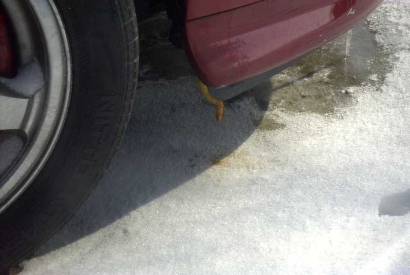
________ at -40f, the oil was thicker than what was in the catchcan.
Are you able to drain the goo through the drain nipple at the bottom of the filter? Mine cannot even drain engine oil at room temperature...
I checked the filter in my fridge, the water is all ice now....and no sign of crack in the bowl

You're in Northern Ontario! Close to Sudbury/North Bay??? I was there last May! Very nice place! I love Canada


")