How me diagnose a DC electrical problem

Status
Not open for further replies.
Joined
Nov 29, 2009
Messages
9,583
So if I remember right direct current flows from negative to positive and the device just takes the amperage it needs. Electrical stuff isn't my strong point, but basically want I'm trying to do is test my fish finder and vhf radio on my boat by connecting directly to the battery itself. How can I do that? Do I just wire it directly to the battery and put an inline fuse on the positive side? I have a radio a vhf radio and a fish finder connected with the grounds daisy chained into one line. The previous owner wired it up like this. Basically the only thing that works is the regular music radio. I have a feeling the fish finder and the vhf radio just don't work anymore. The vhf radio was on the fritz for like a year and I think the fish finder finally shorted out too, but I want to test them before I buy new ones.
 
I'm trying to trouble shoot my vhf radio and fish finder on my boat. Both aren't working, but the regular fm/am radio does work. I have a feeling they both just quit working cause the vhf radio was on the fritz for about a year and I think the fish finder finally shorted out. Electrical stuff isn't my strong point, but if I remember right, direct current flows from negative to positive and the electrical device just takes what it needs. The previous owner has all three devices wired to a fuse block with the ground wires daisy chained together. (I didn't wire it this way) I want to test them, so my question is can I wire them directly to the battery with an inline fuse on the positive side?
 
"Shorted out" is the most overworked term in the electrical dictionary. In cars, except for some old British machines, the negative terminal of the battery is attached to the body and frame. In a boat, except for a metal one, you need a ground path from the battery all the way out to the "appliance". So, you need to measure with an OHM meter from the "appliance" to the negative terminal to see if this path still exists. Don't worry about the direction, red to plus and black to minus is the convention. Then measure with the meter on VOLTS as close to the "appliance" as you can get, inside if necessary, to see if 12 volts is making it to the unit. A corroded connection may show 12 volts to a meter but not allow enough current to run the appliance so turn the unit on to test it under load. Running a wire to the unit from the plus terminal of the battery will also rule out a problem in the plus wiring IF the unit comes on but it's a dangerous thing to do if the wire end hits something grounded. A basic question, do the units light up? If not I'd check all the connections, and the fuse holders. if any, for crud build up.
 
On your VHF radio make sure the cable connections are clean on the inside and outside of connector and threads all the way to the connection on the antenna. (usually PL259 connectors)

If you or prev owner 'keyed' the mike to transmit into a open or shorted antenna cable or connector and blown the RF transmit amplifier, this means the radio is scrap unless a pal knows how to fix it. It may blow an internal fuse or fry a power transistor, etc.

In the hey-day of CB radio everybody tweeked their antennas with SWR (Standing Wave Ratio) meters and antenna matchers. Turns out high SWR on any transmitter affects performance up to the point of damage!
 
Yes, DC electron current flows from neg to pos. No worries connecting it straight to a battery, as long as voltage polarity is observed. I'd separate the gnds for now.
 
Originally Posted By: sleddriver
Yes, DC electron current flows from neg to pos. No worries connecting it straight to a battery, as long as voltage polarity is observed. I'd separate the gnds for now.


Do I need an inline fuse or can I connect it right to the battery?
 
An inline fuse is a pretty good idea. I'd get about a 50 amp "master fuse" for the accessories. Marine supply stores have fuse subpanels; put one of these near the battery (but more accessible) and after your master fuse. For testing purposes you don't have to- have to; it's unlikely the stuff died of a dead short and they could have internal fuses anyway.

IDK about "ground" on a boat, as mentioned above. You could get a car headlight and wire it up where your radio was/ is to test the current carrying capability of the wiring in place. The headlight will draw around 5 amps, a decent enough load test.

The point of putting the fuse at or near the positive terminal is that it shortens the unfused section of wire that could touch ground and minimizes risk.
 
Originally Posted By: eljefino
An inline fuse is a pretty good idea. I'd get about a 50 amp "master fuse" for the accessories.

IDK about "ground" on a boat, as mentioned above. You could get a car headlight and wire it up where your radio was/ is to test the current carrying capability of the wiring in place. The headlight will draw around 5 amps, a decent enough load test.
The stereo has a 10 amp fuse and it works, so I think the load carrying ability is ok, but I like that idea. So you mean I can just get a headlight bulb at the auto parts store for a few bucks?
 
Last edited by a moderator:
> So you mean I can just get a headlight bulb at the auto parts store for a few bucks?

Yes. Or, junkyard might have one.
 
Originally Posted By: sleddriver
Yes, DC electron current flows from neg to pos.


If electrons flow from negative to positive, then why is ground always on the negative side ?

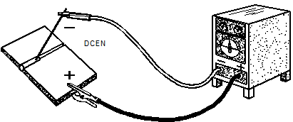
If I have a stick welder hooked up, current flows out the machine's negative terminal - through the ground lead - through the work - up through the electrode - through the positive lead - and back to the positive terminal on the machine. Now in that case, the electrons are flowing from negative to positive like you say, but the current flow is called "Direct Current Reverse Polarity by the welding machine people. If current was truly supposed to flow from negative to positive, wouldn't the welding machine people call that Direct Current Straight Polarity ?

wkh-chapter5-image003.gif
 
wkh-chapter5-image003.gif


The machine in that picture has its leads set up backwards. As you're seeing it in the picture, it is set up electrode negative with the ground lead hooked up to the positive terminal. That is BACKWARDS!
 
Current is just the flow of charge.

Current doesn't flow, current IS the flow. In addition, electrons purely go from lower potential to higher potential. Ground is solely an arbitrarily chosen reference point as to where you set as 'zero'.

I don't think welders are worrying about which way the charge is flowing (in all cases, the electrons going towards the higher potential). They can call either polarity whatever they want.

Sorry, off topic.

To test any of the devices, I would probably my just probe the power input to verify that it is getting the proper voltage. If it is, and you know the source has enough power output, the device is probably shot.
 
Last edited:
Potential difference, and a low resistance path is what's important, not direction of flow which is purely a conventional choice. Electrons (- charge ) flow one way, holes (+ charge) flow the other way, or pos to neg. I was taught "hole flow" in nuclear power training. And at the same time other groups were being taught the opposite flow path. Electrons don't flow, it's the "holes" doing all the work....lol.
 
Finding electric faults starts with electric wiring diagrams. follow the diagram, take notes for what you should be measuring, and what you're measuring in real life, then see what has to be wrong to get that result.

circuit_diagram.png


Here you go, practice on that.
 
The size of the fuse should be based on the size of the wire. If the fuse is too big then the wire becomes the fuse.
 
Originally Posted By: Merkava_4
Originally Posted By: sleddriver
Yes, DC electron current flows from neg to pos.


If electrons flow from negative to positive, then why is ground always on the negative side ?

If I have a stick welder hooked up, current flows out the machine's negative terminal - through the ground lead - through the work - up through the electrode - through the positive lead - and back to the positive terminal on the machine. Now in that case, the electrons are flowing from negative to positive like you say, but the current flow is called "Direct Current Reverse Polarity by the welding machine people. If current was truly supposed to flow from negative to positive, wouldn't the welding machine people call that Direct Current Straight Polarity ?

wkh-chapter5-image003.gif


"current flows positive to negative" is just a convention used widely, and it is the opposite of the direction of electron flow.

With DC welders, the conventional flow of current is used and "straight polarity/ electrode negative" is the widely accepted term used to describe a commonly used set up. It is all just terms being used and makes no difference.
 
Originally Posted By: motor_oil_madman
Originally Posted By: sleddriver
Yes, DC electron current flows from neg to pos. No worries connecting it straight to a battery, as long as voltage polarity is observed. I'd separate the gnds for now.

Do I need an inline fuse or can I connect it right to the battery?
For testing purposes, you can quickly make contact directly to the battery and see if it lights. Or you can go through an extermal fuse. There may be another fuse internally that's blown or an open diode, so you'll have to investigate further.

For permanent mounting, you always need a fuse especially in a boat.

The other guy had a good point. You can use a headlight bulb or even an incandescent tail light bulb, wired in a socket as a simple tester. It will tell you more than a simple voltage check.
 
Status
Not open for further replies.
Back
Top Bottom