Not smart here, but know the answers
Ca is 120/ 240
240 is more efficient - therefore cheaper.
UncleDave....
You are extremely smart.... Zero doubt about that.
Not smart here, but know the answers
Ca is 120/ 240
240 is more efficient - therefore cheaper.
https://forums.tesla.com/discussion/168051/120v-240v-charging-efficiency-answers
Setup:
Temperature: 75-85F (24-29C) in my garage
Equipment used:
- IoTaWatt in the Circuit breaker box, with dedicated monitors per circuit
- Stats running on my phone, querying the car's API
- Gen 2 Mobile Connector charging at 32A @ 240V, or 12A @ 120V.
Technique:
- Charging started in the evening, stopped in the morning. IoTaWatt and Stats were queried to find how much power was drawn from the house panel, and how much was stored in the battery.
- The 240V outlet and 120V outlet are very short runs from the Circuit Breaker box, minimizing power loss in the wiring. The 240V circuit is about 15' of AWG 6, and the 120V circuit is about about 5' of AWG 12.
Results:
At 240V (Measured average about 252V), Stats showed 40.62 kwh added to the battery. IoTaWatt showed 42.5 kwh pulled from the wall. Efficiency = 40.62/42.5=95.6%.
At 120V (Measured average about 126V), Stats showed 10.15 kwh added to the battery. IoTaWatt showed 11.9 kwh pulled from the wall. Efficiency = 10.15/11.9=85.2%
Conclusion
Charging at 240V is very efficient, and noticeably more efficient than charging at 120V. You will pay about 12% more to charge at 120V compared with charging at 240V.
Example: Driving 10,000 miles per year, at 250 Wh/mile, will take about 2500 kwh from the battery. At 240V, you'll pull (2500/0.956) = 2600 kwh from the wall over the year to recharge the battery. At 120V, you'll pull (2500/.852)=2900 kwh from the wall over the year, which is 12% more power and likely 12% more money.
Question for all the smarty pants people like @OVERKILL ....
1st, is CA 110 or 120 v? 220 or 240 v ?
2nd - the real question - Is the cost of charging cheaper with 240v? Someone said something like you lose perhaps 30% due to efficiency with 110v.
Asking for a friend with one of those stupid Teslas... Thanks!
The confounding factor there is that the 240 V circuit uses #6 AWG conductors, whereas the 120 V one uses #12.https://forums.tesla.com/discussion/168051/120v-240v-charging-efficiency-answers
Setup:
Temperature: 75-85F (24-29C) in my garage
Equipment used:
- IoTaWatt in the Circuit breaker box, with dedicated monitors per circuit
- Stats running on my phone, querying the car's API
- Gen 2 Mobile Connector charging at 32A @ 240V, or 12A @ 120V.
Technique:
- Charging started in the evening, stopped in the morning. IoTaWatt and Stats were queried to find how much power was drawn from the house panel, and how much was stored in the battery.
- The 240V outlet and 120V outlet are very short runs from the Circuit Breaker box, minimizing power loss in the wiring. The 240V circuit is about 15' of AWG 6, and the 120V circuit is about about 5' of AWG 12.
Results:
At 240V (Measured average about 252V), Stats showed 40.62 kwh added to the battery. IoTaWatt showed 42.5 kwh pulled from the wall. Efficiency = 40.62/42.5=95.6%.
At 120V (Measured average about 126V), Stats showed 10.15 kwh added to the battery. IoTaWatt showed 11.9 kwh pulled from the wall. Efficiency = 10.15/11.9=85.2%
Conclusion
Charging at 240V is very efficient, and noticeably more efficient than charging at 120V. You will pay about 12% more to charge at 120V compared with charging at 240V.
Example: Driving 10,000 miles per year, at 250 Wh/mile, will take about 2500 kwh from the battery. At 240V, you'll pull (2500/0.956) = 2600 kwh from the wall over the year to recharge the battery. At 120V, you'll pull (2500/.852)=2900 kwh from the wall over the year, which is 12% more power and likely 12% more money.
Charging efficiency in and of itself hardly matters.
Only 240v charging is getting you a useable range overnight.
Isn't CA very high per kwh?
I’m not sure I buy this, especially without a better explanation of the charger topology and it’s effect on the rectified dc and the losses. Is it the same charger for 110 and 220? Are the IGBTs employed differently? Different levels of ripple? Do we have actual waveforms?
Conductor resistance is a thing. Losses increase with the square of current, doesn’t matter if it’s 110 or 220 or something else. You go higher voltage to reduce current.
The report you gave didn’t cite battery %SOC or temperatures. The impedances of batteries do change, and that may be a factor.
The question really is what conditions result in higher losses?
They can be:
1) IGBT switching losses and noise (which will be worse at low current levels)
2) conductor losses - mains power
3) cell (ESR) losses
4) cooling system losses
5) BMS on-state losses
6) BMS balancing energy burned
7) conductor losses (internal to battery and charger)
8) vehicle control system losses
Each of these can be discussed in more detail. Perhaps some time I will.
For now I’ll just address briefly one by one:
1) favors faster charging, as the losses are higher as a percentage the lower you go (though the net may be higher). The topology of the charging converter may also play in here at higher vs lower mains input. I do suspect that all other things being equal, this will drive it, but given that it’s likely to be the same design and topology employed either line-line (220) or line-neutral (120), how much difference and how much it is compared to other factors is hard to say for certain. It’s not like we’re talking one vs three phase, potentially with phase shifting transformers and other goodies to make a much nicer/better dc like you can if we’re talking split phase 220 versus say, three phase 480.
2) favors lower current charging, regardless of voltage. Losses are I^2 *R, and R is not affected by voltage at the same frequency.
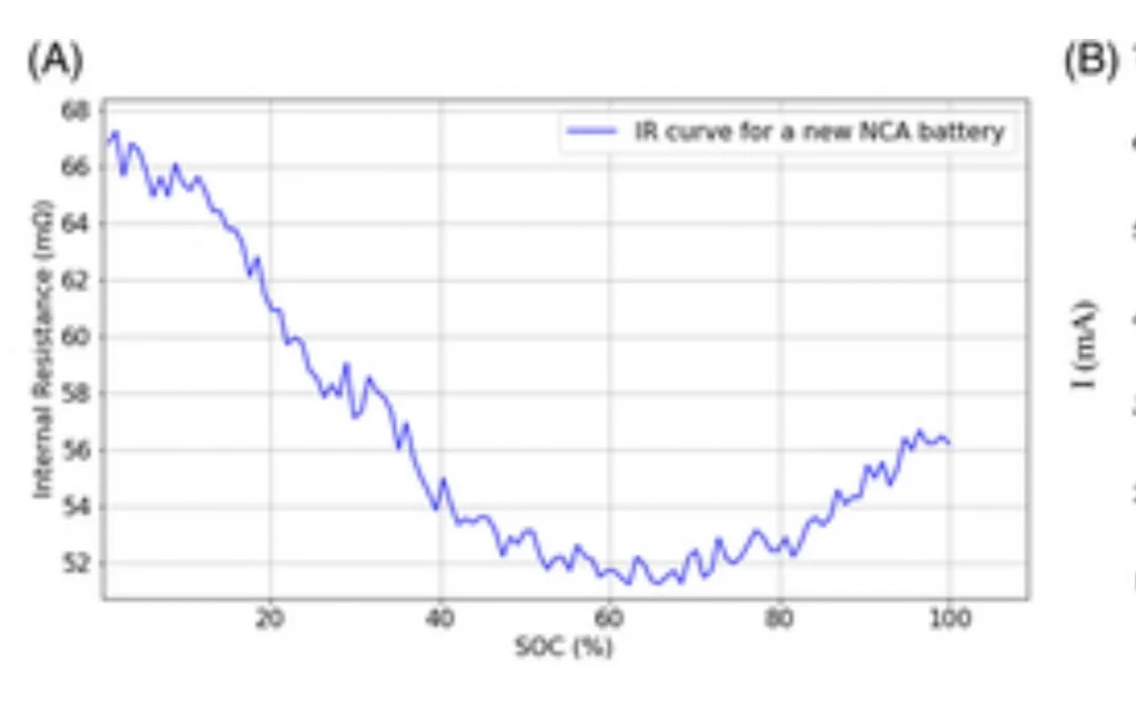
3) favors lower current as in cell losses and heating are also I^2 *R. There are activation losses that drive the need for over potential, and aso it may be U-shaped.
Example of an impedance curve for NCA cells:
So there can be a greater than 10% difference in ohmic losses based just on what the starting and ending SOC is.
4) This depends upon the approach used for cooling system operations while on. If it’s always on, and there’s a minimum flow rate, it’s going to be a higher percentage at lower charge rate.
5) irrelevant to charging voltage. Sunk cost.
6) Assume tesla has set resistive balancing. Thus the losses are proportional to cel group voltage regardless of charging input power. A faster charge will drive a higher overpotential and marginally higher energy burn per ohms law.
7) favors lower current levels
8) constant value irrelevant to mains power in.
In the end I have no doubt that #1 could drive single percentage point efficiency drops favoring higher voltage input and higher current.
No way I’m buying the 10% difference in favor of 240 without more/better explanation and tracing as to why... unless the onboard charger is just that bad.
Technical commentary and rebuttal welcome.
Spot on. The reason for my post.I’ll be interested to see what else you find. I think understanding the ins and outs of this is good info for us all.
It's the way it's always been. If you think that's bad Japan has different standards on the same island. There may also have been an old school perception that 120 was tolerably non-lethal if you took it directly.Why do we in this country use 110/120 volt 60 cycle (hertz) and all Europe uses 220/240 volt 50 cycle (hertz) power?
I don’t know. Just asking.
A fleet of EV commercial vehicles designed to be used with 480 volt
3 phase electric system would bring what to the table????
Funny you mention being at end of long street. We were at beginning of long street and were blowing out bulbs and a tv or two. I measured 130-135vac. Power company was turning up voltage at beginning of circuit/street so ppl at end would have enough. Very arrogant power company told me "things run better on higher voltage" and just buy 130 v bulbs! They finally came out, measured voltage, and installed another transformer. Just shows you gotta check everything these days.Basically the higher the voltage the lower the line losses from resistance. That's why at the power plant it goes out at 360 thousand volts and eventually gets stepped down to 240. They use 220/240 intermittently, you basically should have about 240, but if you're at the end of a long street the voltage might drop down to 220 and that's still acceptable.
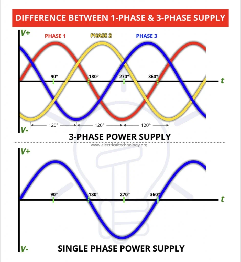
Very informative- thanks!There are a variety of benefits associated with three (or polyphase) power. Some are related to motor and magnetic design, but the main benefit for charging systems is the ability to carry more power on fewer/less conductor, and provide cleaner dc with less ripple.
Here’s an example of split phase (single phase) vs three phase. Recall that AC power is sinusoidal in voltage and current.
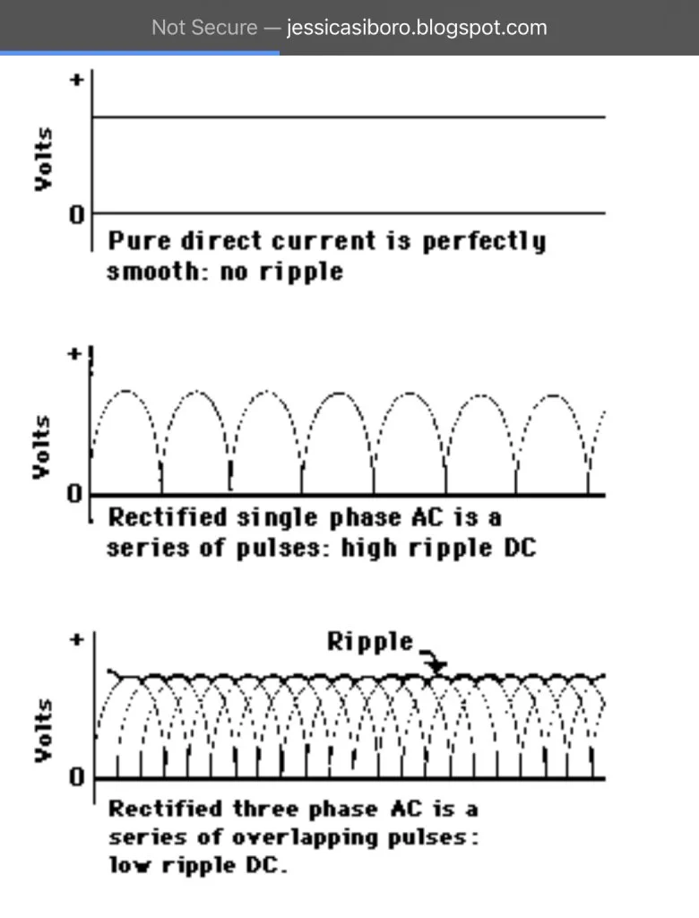
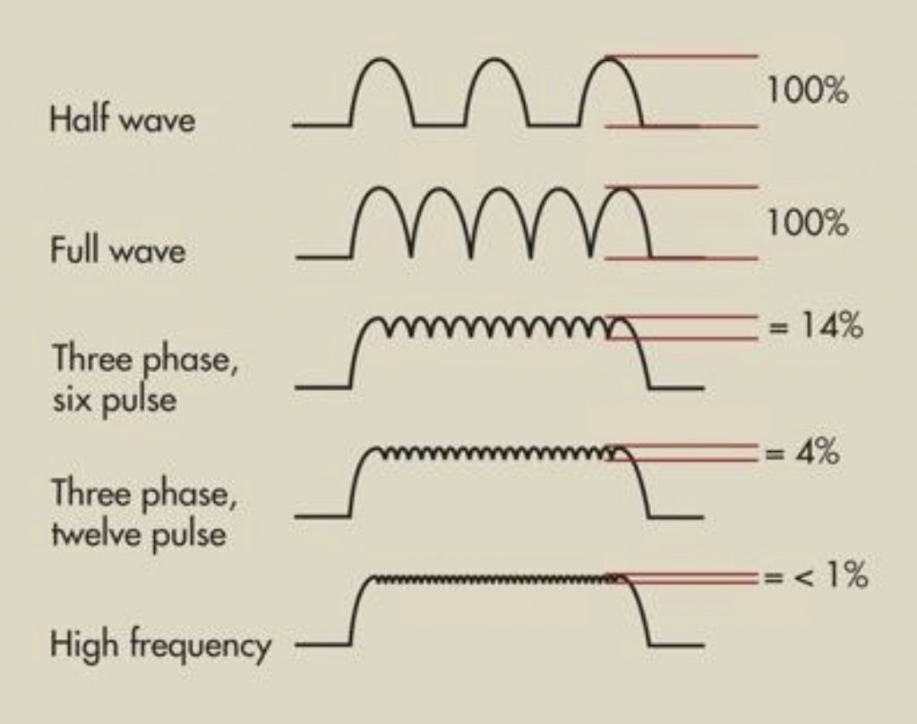
Rectifying dc is the process of taking the alternating (AC) sinusoid, and making it into direct current which for the sake of this, is only positive offset. Rectification of single and three phase looks like this:
Note how bad the ripple is for the single rectified phase. Three phase overlays all the ripples and has significantly less. It’s “cleaner”. There can be polyphase rectifiers that are fed via phase shifting transformers to be even cleaner. Ripple is not good for batteries. I wouldn’t doubt that some larger charging stations might consider more phases.
Some examples:
In the end, the more phases/pulses, the cleaner the dc waveform, the easier to filter and smooth, the better it is for batteries and other equipment. Ultimately it’s a balance of cost, power quality, harmonics, size, efficiency, etc.
But feeding power with three phase, for loss that can take it, will be efficient conductor-wise and from a magnetic standpoint for motors and whatnot.
Why do we in this country use 110/120 volt 60 cycle (hertz) and all Europe uses 220/240 volt 50 cycle (hertz) power?
I don’t know. Just asking.
if you're at the end of a long street the voltage might drop down to 220 and that's still acceptable.
PECO in Pennsylvania is very expensive, too. Customers are paying off loses sustained by PECO's failed nuclear power plant, not the shareholders/owners. Nice to have your loses paid for by somebody else.Absolutely; 120v gets my car 3 to 4 MPH. 240v with the NEMA 14-50 recepticle gets 28 to 32 MPH.
The dual motor cars can charge faster...
My question was not about charging speed; it was about the efficiency of delivering the power.
I did not know if there was a cost difference between 120v and 240v.
In my case, my cost is very low because I installed solar a few years back.
Otherwise, electricity costs in CA are among the highest in the nation.