GON
$175 Site Donor 2026
I have a 2004 Lincoln Navigator that had its engine replaced by a mechanic who knew some things but was challenged in doing things to standard. I have a few threads on BITOG about the Navigator.
After a bunch of issues, I drove the SUV from a transmission shop in Illinois to Washington state, towing a dual axle 16' enclosed trailer without issue. About three weeks ago, I decided to drive the SUV to work, about seven miles from my home. On the way to work I had a weird reaction from the gauges on the dash, just for a second. I went to work, and when it was time to go home, another wacky gauge issue, and the engine died. I was able to get the SUV running and parked the SUV at work. I have another vehicle and went home.
At home, I was unable to find my volt meter. I have about six of them, but they are boxed up. I didn't want to buy another meter. I did have my jump box handy, so I returned to the SUV and hooked up the jump box. The SUV started. As soon as I pulled the jump box the SUV died. I pulled the battery, took the battery home, and put the battery on a charger. Battery charged and passed the battery charger's test.
I put the battery in the SUV. The SUV started, while running, I pulled the ground cable off the battery, the SUV died. I still hadn't found my meter, but I assume a bad alternator. I ordered a replacement alternator from Rock Auto. Only one new Remey in stock, it was in Miami, and took nine days to arrive. No issue, I was working out of state and in no hurry for the alternator to arrive.
Yesterday was the first opportunity to replace the alternator. I only had about 90 minutes before I had other stuff to do (like cook dinner for my Wife). I did find my volt meters. I went to work, started the SUV, it showed 12.5vdc with engine running. Signs of a bad alternator (or wiring). I drove home, and just for fun I measured the volts again with the SUV running, I was now seeing 13.9vdc. Hummmm. I decided to replace the alternator. Although I have not seen many bad alternators come to back to life, I thought it would be best to replace the alternator.
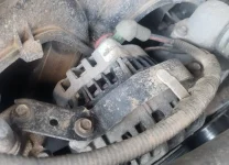
First thing I noticed when I went to pull the alternator were two bolts sticking out of the top of the alternator with nothing secured by the bolts. Next thing I notices was the serpentine belt was old, the mechanic that swapped the engine was supposed to replace the serpentine belt with a new belt I provided. I replaced the alternator, and would later investigate the top two bolts. I also felt uncomfortable that only two bolts held in the alternator, both bolts on the bottom. I don't recall ever replacing an alternator with less than three mounting bolts.
I replaced the alternator, started the SUV, and only 12.5vdc. Not what I wanted to see. I did a visual inspection, nothing visually showing why the alternator was not providing voltage. What stumped me most of all was why no "battery" dummy light showing on the dash. After dinner, I looked at the parts catalog for the SUV and discovered a top mounting bracket is required for the alternator. Bracket is ford OEM 2L7Z-10153-BA. Part is discontinued. Search on Ebay, none listed for sale or completed ever. The issue is the engine in this SUV is a high demand engine, pick parts don't typically have the engine still in the vehicle, so I have some work to find this bracket.
I thought maybe the bracket helps supply a ground, and that could be the issue. I did some more research last night and discovered Ford does not let an alternator just "do its job". Ford employs a smart charge system, so the PCM tells the alternator when to release amps/ volts. So now I think I may have a bad replacement alternator, cable/ wiring issue, ground to the alternator issue, or now add a PCM problem into the mix.
This afternoon I start to do a deeper inspection. I see the two fusible links in the wiring harness from the alternator to the battery. I also see where the wiring harness connects to the battery, electric tape. I pull off the electric tape and see what I am confident is the problem. Where the alternator positive power harness connects to the battery terminal, is connected to the harness that then goes to the starter...... is connected with some sloppy solder. I take a closer look, and discover the solder is not holding the connection, and there is not a solid, or even a semisolid connection from the alternator to the battery from the positive cable harness.
I haven't decided if I will repair the harness or replace the harness with a new one. But I do know that one is at risk more and more outsourcing repairs on their vehicles. Not many Travs, Clinebargers, Wrenchturners, Timmermastechs, and the likes out there anymore.
This video from South Main Auto was very helpful in understanding the Ford "smart charge system". Especially on why there was no battery light or check engine light displaying on the dash.


After a bunch of issues, I drove the SUV from a transmission shop in Illinois to Washington state, towing a dual axle 16' enclosed trailer without issue. About three weeks ago, I decided to drive the SUV to work, about seven miles from my home. On the way to work I had a weird reaction from the gauges on the dash, just for a second. I went to work, and when it was time to go home, another wacky gauge issue, and the engine died. I was able to get the SUV running and parked the SUV at work. I have another vehicle and went home.
At home, I was unable to find my volt meter. I have about six of them, but they are boxed up. I didn't want to buy another meter. I did have my jump box handy, so I returned to the SUV and hooked up the jump box. The SUV started. As soon as I pulled the jump box the SUV died. I pulled the battery, took the battery home, and put the battery on a charger. Battery charged and passed the battery charger's test.
I put the battery in the SUV. The SUV started, while running, I pulled the ground cable off the battery, the SUV died. I still hadn't found my meter, but I assume a bad alternator. I ordered a replacement alternator from Rock Auto. Only one new Remey in stock, it was in Miami, and took nine days to arrive. No issue, I was working out of state and in no hurry for the alternator to arrive.
Yesterday was the first opportunity to replace the alternator. I only had about 90 minutes before I had other stuff to do (like cook dinner for my Wife). I did find my volt meters. I went to work, started the SUV, it showed 12.5vdc with engine running. Signs of a bad alternator (or wiring). I drove home, and just for fun I measured the volts again with the SUV running, I was now seeing 13.9vdc. Hummmm. I decided to replace the alternator. Although I have not seen many bad alternators come to back to life, I thought it would be best to replace the alternator.
First thing I noticed when I went to pull the alternator were two bolts sticking out of the top of the alternator with nothing secured by the bolts. Next thing I notices was the serpentine belt was old, the mechanic that swapped the engine was supposed to replace the serpentine belt with a new belt I provided. I replaced the alternator, and would later investigate the top two bolts. I also felt uncomfortable that only two bolts held in the alternator, both bolts on the bottom. I don't recall ever replacing an alternator with less than three mounting bolts.
I replaced the alternator, started the SUV, and only 12.5vdc. Not what I wanted to see. I did a visual inspection, nothing visually showing why the alternator was not providing voltage. What stumped me most of all was why no "battery" dummy light showing on the dash. After dinner, I looked at the parts catalog for the SUV and discovered a top mounting bracket is required for the alternator. Bracket is ford OEM 2L7Z-10153-BA. Part is discontinued. Search on Ebay, none listed for sale or completed ever. The issue is the engine in this SUV is a high demand engine, pick parts don't typically have the engine still in the vehicle, so I have some work to find this bracket.
I thought maybe the bracket helps supply a ground, and that could be the issue. I did some more research last night and discovered Ford does not let an alternator just "do its job". Ford employs a smart charge system, so the PCM tells the alternator when to release amps/ volts. So now I think I may have a bad replacement alternator, cable/ wiring issue, ground to the alternator issue, or now add a PCM problem into the mix.
This afternoon I start to do a deeper inspection. I see the two fusible links in the wiring harness from the alternator to the battery. I also see where the wiring harness connects to the battery, electric tape. I pull off the electric tape and see what I am confident is the problem. Where the alternator positive power harness connects to the battery terminal, is connected to the harness that then goes to the starter...... is connected with some sloppy solder. I take a closer look, and discover the solder is not holding the connection, and there is not a solid, or even a semisolid connection from the alternator to the battery from the positive cable harness.
I haven't decided if I will repair the harness or replace the harness with a new one. But I do know that one is at risk more and more outsourcing repairs on their vehicles. Not many Travs, Clinebargers, Wrenchturners, Timmermastechs, and the likes out there anymore.
This video from South Main Auto was very helpful in understanding the Ford "smart charge system". Especially on why there was no battery light or check engine light displaying on the dash.
")