Why did North America not use 220v

Status
Not open for further replies.
Originally Posted By: Dave Sherman
If they were in phase, you would get zero volts, not 240.


Um... if you had two hot leads at +120 V draining to the same neutral and both hots were in phase, you'd have...

wait for it...

+ 120 V. You'd have double the current capacity, but you'd still have 120 V.
 
Originally Posted By: leeharvey418
Originally Posted By: Dave Sherman
If they were in phase, you would get zero volts, not 240.


Um... if you had two hot leads at +120 V draining to the same neutral and both hots were in phase, you'd have...

wait for it...

+ 120 V. You'd have double the current capacity, but you'd still have 120 V.


If both hot leads were at +120 with respect to neutral at the same moment in time, you'd have 120 volts with respect to neutral all right, but you would not have 240 volts from hot to hot, you would have zero.
 
Originally Posted By: badtlc
Originally Posted By: Vikas
Why are you "adding" the two voltages? Remember the term "potential difference" way back from middle school? You need to subtract!


nvermind. thought this was a reply to me.
The reply WAS for you and IS still for!

Voltage is measured between two points. If the two points have the same voltage with reference to a third (or neutral) point, the voltage difference between those two points will be zero. Thus if the 2 legs were in phase, the voltage *between* the two legs would be zero.
 
Last edited:
I think badtlc's confusion is he sees the relationship between L1, L2, and neutral this way:

L1
+
120 cos angle 0
-
N
+
120 cos angle 0
-
L2

So he insists there's no phase difference between L1 and L2. However, he overlooks that with respect to neutral, L1 and L2 are not in phase, but are inverted from each other. This could be illustrated this way:

L1
+
120 cos angle 0
-
N
-
120 cos angle 180
+
L2
 
Originally Posted By: badtlc


Not to rain on your parade but you are using the false assumption that one leg is at 180 degrees phase angle. That is not true. Since you have access to an oscilloscope, you can prove this to yourself. Use red and black leads. Attach the red lead to one end of the scope and black to the middle. Then move BOTH leads to maintain proper polarity direction. This requires moving the red lead to center tap and the black lead to the end of the coil.

Your scope will show two 120V sine waves in phase. If they were not in phase, they'd subtract from each other (magnitude wise) and cancel each other out. They are in phase and as such will add to each other (magnitude wise) and produce a 240V. When you are measuring end to end, you are not subtracting one voltage from the other.


Not to rain on your parade, but your are using the false assumption that your oscilloscope example will show definitively that they are in phase. This is not true. The scope will always show the same waveform if it's triggering on a rising or falling edge. It has no knowledge of the phase relationships between the two legs, and if you are changing connections, even if you do flip the wires, it will still show the same waveform.

Here, I can show you exactly what I'm talking about, using the aforementioned oscilloscope. I have a center-tapped transformer, which is a little safer than trying to go stick the scope probes on the two buses in the junction panel. One channel is on one leg, the other channel is on the other leg. The channel common is tied to the center tap ("neutral"). Note the two signals are NOT in phase.

Originally Posted By: badtlc

I'm not sure why you are having a hard time understanding this as you appear to be a smart enough person with regards to the math but you don't seem to understand how to apply it properly.


I'm not sure why you are having a hard time understanding that with respect to neutral, they are not in phase, which is what prompted this whole discussion. The math is correct.
IMG_0344.jpg
 
Originally Posted By: badtlc
Originally Posted By: jrustles
Originally Posted By: badtlc


But what do I know. I'm only an EE and design power distribution installations for everything from houses to refineries and power plants.


how do you feel about 'technical power' in homes; ie two hot 60V, where L1 and L2 of the split-phase system is always balanced.

Is there ANY advantage is eliminating current flow through the home's ground path?


I have never seen such an installation. Doesn't make any sense if they are still producing 120V source voltage. The current flow is the same regardless as long as voltage applied is the same magnitude. The current doesn't flow through the ground path, it flows through the neutral & hot conductors unless there is a ground fault.


On US Navy ships, standard 120V AC outlets have 2 60V hot legs. Obviously "common" is not bonded to ground.
 
Originally Posted By: cbear
Originally Posted By: badtlc
Originally Posted By: jrustles
Originally Posted By: badtlc


But what do I know. I'm only an EE and design power distribution installations for everything from houses to refineries and power plants.


how do you feel about 'technical power' in homes; ie two hot 60V, where L1 and L2 of the split-phase system is always balanced.

Is there ANY advantage is eliminating current flow through the home's ground path?


I have never seen such an installation. Doesn't make any sense if they are still producing 120V source voltage. The current flow is the same regardless as long as voltage applied is the same magnitude. The current doesn't flow through the ground path, it flows through the neutral & hot conductors unless there is a ground fault.


On US Navy ships, standard 120V AC outlets have 2 60V hot legs. Obviously "common" is not bonded to ground.


So there is 60 V from neutral to ground? Is that to ensure the neutral never gets grounded?
 
Probably to reduce the risk or shock or salt water on the outlet. Salt water is as good as copper for an electrical path.

I have in the past used a transformer backwards to reduce the voltage to around 60v and applied it to my bird feeder pole, insulated form the ground, to keep the squirrels off.
smile.gif
 
I read it to be 120v split phase. 120v leg-to-leg, with no grounded neutral.

Originally Posted By: PSS
So there is 60 V from neutral to ground? Is that to ensure the neutral never gets grounded?
 
The way I understand it is it's 220v single phase.

Just because the O-scope shows one trace at a potential above the ground tap and one below doesn't mean they are out of phase. It simply means they are moving in different "directions" relative to the center tap potential.

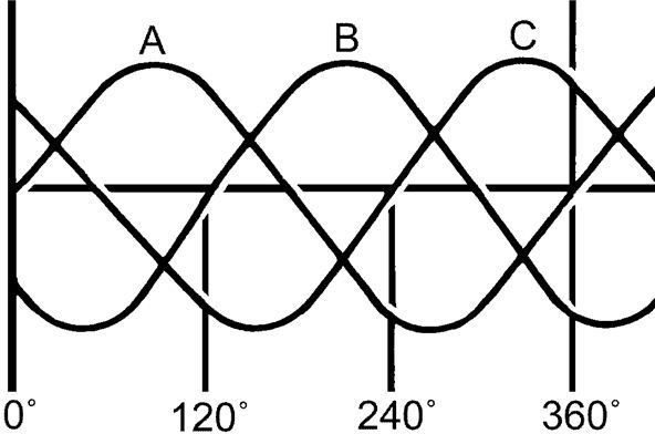
Here is how a three phase o-scope trace looks

46d19c853680e2ac490c9edae4aa409cd74e4ac4_large.jpg


A more accurate description of the 220vac in your home would be SPLIT PHASE. The single phase is split because you take one split between one hot wire and ground. You take the other split of the same phase between the other hot wire and ground.

Ground is not the lowest potential. You can reach voltages above or below the ground potential. Therefore, just because one trace is below ground potential by the very same magnitude as the other trace is above ground potential does not imply they are 180 degrees out of phase. You are looking at the relative potential of each hot lead on the very same single phase.
 
Exactly. It's not 180 degrees out of phase, but splitting the potential of a 220v single phase supply.

Originally Posted By: kschachn
I read it to be 120v split phase. 120v leg-to-leg, with no grounded neutral.

Originally Posted By: PSS
So there is 60 V from neutral to ground? Is that to ensure the neutral never gets grounded?
 
Originally Posted By: javacontour
The way I understand it is it's 220v single phase.

Just because the O-scope shows one trace at a potential above the ground tap and one below doesn't mean they are out of phase.


Yes, it really does. If they were in phase (i.e., zero phase angle between them), then you would not have 240 volts available, and both signals would be overlapping each other. The fact that they are opposing each other shows that they are 180 degrees apart. It really is very simple. They are out of phase by virtue of the split secondary.
 
Some of you are claiming to have graduated from electrical engineering school. I hope it was long time ago and have forgotten most of it. I certainly don't remember most of it!
 
Originally Posted By: SHOZ
Coming off one transformer it has to be single phase.


There are such things as 3-phase transformers, but yes, this is single phase. Early on, somebody said the two hots are 180 degrees out of phase WITH RESPECT TO NEUTRAL, and some others say no, they aren't. Whatever.
confused.gif
 
Again, more unfortunate, or in this case, overloaded terms.(EE degree from long ago, seldom used today, and also a Software Engineering degree, where terms are, unfortunately, overloaded in that field as well.)

The 220V source is single phase. As you (and perhaps others) indicated, if you look at the waveform across L1 and L2, you see the single phase 220v. If you look at either split of that L1-Neutral vs L2-Neutral, they are 180 degrees out of phase with one another.

Single phase source, but your frame of reference determines how you see it.

Any 110v device sees single phase, regardless which 110v side it's on.

Likewise, any 220v device also sees single phase between L1 and L2.

Let's not get going with conventional current flow vs electron flow. It was hard enough unlearning what I knew to pass some Army tests that treated DC circuits as if current flow and electron flow were in the same direction.

33.gif


Originally Posted By: Dave Sherman
Originally Posted By: SHOZ
Coming off one transformer it has to be single phase.


There are such things as 3-phase transformers, but yes, this is single phase. Early on, somebody said the two hots are 180 degrees out of phase WITH RESPECT TO NEUTRAL, and some others say no, they aren't. Whatever.
confused.gif
 
Originally Posted By: cbear
As far as the shipboard use, my guess is ground is isolated so that it doesn't increase galvanic corrosion of the hull.


High impedance ground where needed with transformers providing galvanic isolation. Ungrounded delta configuration 450 (yes 450, 440 nominal actually) 3ph.

Need to go back and read the op.

But I'm a ChE who moonlights as an EE.
 
Originally Posted By: kschachn
Please show me the amp meter attached to your house and explain how you are paying for amperes.

I will concede that my degree is a BSME, not BSEE. But I did work for several years in the electrical power generating industry.

Originally Posted By: d00df00d
Originally Posted By: kschachn
That's gotta be one of the dumbest posts I've ever seen. You pay for watt-hours, not amps. It's the same regardless of the voltage.

You pay for power, plain and simple.

Watts = volts * amps.

More volts means fewer amps needed to get the same wattage.


Actually, business and industry often pay for kVA, not kWh, power factor (could be off by 20%) being the difference.

But in the us it seems that we're not charged that way (yet).
 
Well I did say "house"
wink.gif


Originally Posted By: JHZR2
Originally Posted By: kschachn
Please show me the amp meter attached to your house and explain how you are paying for amperes.

I will concede that my degree is a BSME, not BSEE. But I did work for several years in the electrical power generating industry.

Originally Posted By: d00df00d
Originally Posted By: kschachn
That's gotta be one of the dumbest posts I've ever seen. You pay for watt-hours, not amps. It's the same regardless of the voltage.

You pay for power, plain and simple.

Watts = volts * amps.

More volts means fewer amps needed to get the same wattage.


Actually, business and industry often pay for kVA, not kWh, power factor (could be off by 20%) being the difference.

But in the us it seems that we're not charged that way (yet).
 
Status
Not open for further replies.
Back
Top Bottom