
My remote bypass full flow project

Status
Not open for further replies.
Joined
Nov 27, 2006
Messages
18
Location
Australia
hi guys
I've been working on my little bypass project and its almost complete.
but the other day as I was thinking on the royal throne I decided to ask here on this wonderful forum if it would work before I installed it.

as you can see I have made a plate to fit between the bypass filter with a carburetor jet in it to minimise the flow.
I also made some nipples with 3/4 thread on one side and a m20 thread on the other to accommodate for the filters.
I have no doubt that the full flow will do its job but I'm not sure if the carby jet with a 1mm hole is enough and will there be enough pressure difference to allow oil to circulate or will it just sit in the filter once it fills.
am I making sense?
by the way castrol rocks I use it for all my lubrication needs but I don't think the banner is working clicked on it twice and nothing happened.
 
Besides getting the hole the right size, what ever that is you may have an issue of how the system works. Right now it appears that you will have to wait for the full flow filter to get used for a while to get some back pressure built up so that finally some of the oil will go through the bypass. Since you are in an experimenting mode you might want to consider giving the bypass filter it's own separate return hose to a non-pressure area like the pan just below the oil level line. This way you can field engineer the system to perform exactly like you want. In other words doing it this way you isolate the two functions so you have at least a chance to figure out what is going on. The Amsoil dual bypass system has an orifice with a spring and a plunger to try to do this and I think that you also have to wait for the full flow filter to generate some back pressure to get the bypass filter working. This is something I would not want on my car. I think it's best to keep the return flows in their individual circuits.
 
zydawn

Let me first compliment you on your machining/fabricating skills.

As Lonnie said there is no need to choke the flow to your bypass element when setup in parallel like this. The flow will naturally divide based on the comparative resistance between the two filters as the oil sees it. Since the full flow has virtually no resistance to oil flow (normally) it will always get the lion's share.

Without a reactive component (like the sprung biasing valve that Lonnie mentions) the only solution is to reuse the same full flow element. It needs to be a reactive component to compensate for the changing viscosity of the oil. Something that will attempt to maintain a 2 PSI differential across both filters by limiting the oil flow to the full flow.

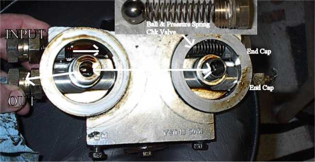
Here's what Amsoil used to use. They also, at one time, used this same internal biasing valve on a Permacool casting just like yours. This was before they graduated to their more substantial mounts. Now they use a like component, but it has a small hole drilled in the ball section.

Note the flow routing. The full flow is mounted on the right side.

amsoilbypassold.jpg


..and if no one has said it yet ....
welcome.gif
 
thanks for that
I will take your advice and put a separate return line in.
any idea what a safe volume of oil flow would be for the bypass filter.
its a baldwin b7034 but couldn't find any info on it.
I think a 1mm hole might be a bit big to start with.
thanks
 
With a separate line you could start with an 1/16th diameter hole, or maybe one drill size lower. It's easier to drill a hole bigger than the other way around.
 
I don't see how this will work with this mount also serving as a feed for the full flow filter. Unless he can put a plug in between the two filters in the return line "tunnel". Only in that way (if I'm reading this correctly) can the returns be sequestered. Otherwise the outlet of the full flow will naturally go to the zero pressure return to the amount that it can ..and you'll be in the same situation as before ..but with no flow through the bypass.

That is, right now it's common supply and common return. Add another return ..this will not change. Both returns will still be common to the return rail.

I may have missed something here
dunno.gif


Another alternative is to setup up the Permacool dual mount with two bypass filters and use a Permacool sandwich at the engine. The poppet relief valve will provide the differential to induce the flow through the bypass filters. The flow will be little when cold and more when hot (whatever 2psid will provide).

f1971ce8.jpg
 
your right again Garry.
had to spend a few more moments on the throne and think I have a solution.
A 16mm rod with a rubber O ring at then cut a channel to allow for the oil that returns from the bypass filter.
bit hard to explain but I will post pics tomorrow.
I've also decided to go with a .7mm hole for the bypass.
one question I do have which is a bit of the topic.
the Mazda K8 engine is known for low oil pressure, cant do much to the existing pump I don't think , but what about an external pump for the filters or maybe a in line pump.
is there a inexpensive way?
any additional pump would have to be electric as there is no room on the engine for a pulley.
 
Can be done, surely. It's expensive. Mocol makes a pump designed for continuous duty for cooling differentials and transmissions that don't have their own pump.


mocpmp.jpg
 
you might all be thinking, why don't you just buy the darn thing instead of trying to build one.

well I have two answers for that.

1 its fun, I get a certain amount of pleasure building things myself and even more pleasure when they work.

2 cost ,down here in the land of OZ there seems to be very few bypass filters and mounts and so there is a premium to pay. I have been fortunate enough to source most the parts from eBay and even after postage the total cost so far has been less than AU$100.
well I completed the plug that will be used to stop the flow and have inserted the jet onto the square aluminium plate. The smallest jet I had was a stromberg .33 main jet I hope its small enough.
I have inserted a couple of photos so all can admire my handy work.
plugfd6.jpg


platere6.jpg


I still have a couple of questions though.
could I use copper pipping and how much flow is to much for the bypass.
 
.33? In what measure? One Amsoil mount uses a .030" restrictor. They put it on the outlet so that any stray particle won't clog it.

Copper lines are fine ..something like cooper tubing for a mechanical pressure gauge would work. You may see elevated copper for a bit if you do UOA. It should handle any vibration it may experience. It should also lower your flow a bit.

Oz ..and the rest of the aligned industrial economies, appear to have many gaps in availability of some products. We just don't get all the neat stuff that others have. You get to buy all those neat tall and skinny tyres ..that our DOT feels aren't good for us ..but cross a border and they work just fine. Oil in Canada ..filters in the USA
dunno.gif


I want these. I can't get them without paying way too much.
rangemaster.jpg
 
plugfd6.jpg


I'm a little disoriented here. You only need to put a partition between the filters. A "plug" ..perhaps epoxied in with the proper sealant (we have JB weld or other like bonding agents). The inlet is common ..and then you just plumb your separate return flows at either end of the return rail.

Pardon my crude drawing
shocked.gif


the jet had 33 on it so I think it was .033".
I probably should have put it on the outlet , I might still make another nipple with a jet in if I find the flow is to great ,I could have used just a standard plug but I wanted it to be removable in case I ever want to use the adapter for some other purpose in the future and I wasn't sure if I could just epoxy a plug in, I was concerned that with the pressure and heat it might work loose.
If you ever need something from here that you cant get there let me know , Ive been trying to get some of that Auto RX , I have been told there is a supplier here but he hasn't contacted me yet.
 
If you put the restrictor on the outlet (checking in resoning - imagine thought cloud) you should see the same pressure on either side of the plug.

.033 would be a good size ..or so I reason.
 
who was it that said
we do this not because its easy.
we do this because its hard. I think it was JFK.
I know he was referring to the moon.
I think your right but on the plus the filter will never see more than a couple of psi (maybe).
at some point I plan to build another and I promise I will do a better job.
 
I salute your courage and unwavering commitment to this project.

You're doing fine
dunno.gif
We're just discussing the stuff that you haven't run across yet from experience. We all gained our experience doing exactly what you're doing. Taking an idea and just grabbing the bull by the horns and figuring out what happens. At times stuff works out pretty spot on with our expectations. Other times, we realize that we didn't take something into account and we go back to the drawing board.

I can fill a good size dumpster with my failures. Does it stop me from trying?
smile.gif
 
Status
Not open for further replies.
Back
Top Bottom