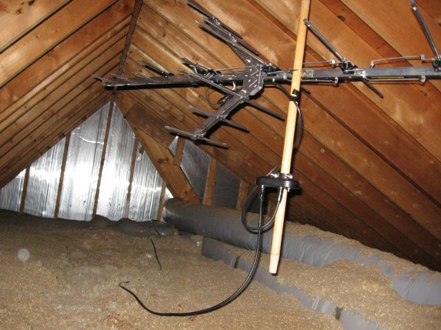
Long range attic antenna?

Status
Not open for further replies.
My comment on coax goes back to my college days installing satellite dishes. Pretty much any RG-6 worked great, but the quality of RG-59 varied greatly. The better stuff was 20 gauge, the cheaper stuff was 22 and usually had the formed on connectors and would be the 50 ft roll you'd buy at Wal-mart under a brand like GEMINI. I'd always replace any RG-59 I came across unless the run made it too difficult or impossible. Never had any issue having to reuse the 20 gauge stuff but the 22 would cause problems.

That may not translate to antenna use, since a satellite receiver sends 24 volts up to the LNB to power it.
 
Originally Posted By: Papa Bear
The signal current is in milliamps (microamps) and I still believe the signal loss is not due to centre conductor gauge but rather the stray capacitance inherent in coax cable.
http://www.allaboutcircuits.com/textbook/alternating-current/chpt-14/characteristic-impedance/


You mean stray capacitance from an improperly connected connector, or an unterminated stub? Should be no stray capacitance in coax--otherwise it's not a coaxial structure.

Capacitance and inductance are lossless components. At least ideal ones. In reality, inductors have losses (usually resistive) and capacitor losses are either resistive or dielectric. But at most TV frequencies the dielectric losses are very low. In this case, the loss of the distributed capacitance is... from the copper wires making the plates of the capacitor.

If you look up various kinds of coax, for a given impedance, you'll find that they all have roughly the same amount of pF per foot, going from thin to thick--the reduction in loss is not from reducing capacitance per foot but by increasing the surface area of the conductors.
 
Originally Posted By: supton
Originally Posted By: Papa Bear
The signal current is in milliamps (microamps) and I still believe the signal loss is not due to centre conductor gauge but rather the stray capacitance inherent in coax cable.
http://www.allaboutcircuits.com/textbook/alternating-current/chpt-14/characteristic-impedance/


You mean stray capacitance from an improperly connected connector, or an unterminated stub? Should be no stray capacitance in coax--otherwise it's not a coaxial structure.

Capacitance and inductance are lossless components. At least ideal ones. In reality, inductors have losses (usually resistive) and capacitor losses are either resistive or dielectric. But at most TV frequencies the dielectric losses are very low. In this case, the loss of the distributed capacitance is... from the copper wires making the plates of the capacitor.

If you look up various kinds of coax, for a given impedance, you'll find that they all have roughly the same amount of pF per foot, going from thin to thick--the reduction in loss is not from reducing capacitance per foot but by increasing the surface area of the conductors.


Surface area is important if there is current flowing.
There is almost immeasurable (small) current in an antenna cable.
I'm sticking with the capacitance rule. The best cable has less capacitance. A capacitor to ground won't affect DC but it will place a load on an AC signal - dependant upon Pf/ft & frequency
I have not heard where conductor gauge is very important in signal loss (within reason) https://www.google.ca/?gws_rd=ssl#q=why+do+you+lose+signal+strength+in+long+coax+runs

"Capacitance and inductance are lossless components."
No they aren't .. they are loads to AC. How do you think a speaker crossover works ??
 
Originally Posted By: JHZR2

Do you have to terminate it to get that performance or just let it be open ended?


Do you mean having an f connector on the end of the coax? The roll I bought had them on it already.

Originally Posted By: Papa Bear
Why does it have to be an attic mount antenna? Why not on the roof?


The reason I didn't mount it outdoors was for two main reasons. It would have been difficult to mount it on the side of the house where I wanted it, and I was concerned what the weather would do to it over the years.

Here it is with the preamplifier installed. The power supply for this one stays cool to the touch and the tv is scanning over 40 channels now. Oddly enough, a channel that was coming in weak from the other direction actually doesn't come in at all with the preamp on. WSKY is still not coming in strong enough, but I'm getting all the other ones at a decent level now.

 
That antenna would last decades outside.

My power supply is a little warm.
It is producing a few watts so some heat is to be expected.

I mounted my HBU-22 right on the plumbing vent pipe and ran the coax through the pipe into the attic (have to drill a small hole in the pipe and fish it through)

Slick, neat, cheap.
 
It's funny you mention the plumbing vent pipe. When installing this antenna in the attic, I noticed everything looked wet where the vent pipe was. It comes through the very edge of the upper roof. Ater getting on the roof to inspect it, I found a hole around 2x1.5" in the gasket around it.
That could have gone unnoticed for years and I hate to think how many years it's been already.
 
Originally Posted By: supton
Originally Posted By: sleddriver
99% of the signal itself travels on the skin of the copper center conductor, not inside of it.


Gotta quibble here: All of the current is on the "skin" of the center conductor--and on the skin of the outer foil also. It's still electricity, current flowing on the center conductor has an equal but opposite current on the foil. And, the current on the outer foil flows on the inside of the foil, not the outside--those currents are trying to be as close as possible.

Here's where the loss is: the inner conductor is a smaller diameter than the outer conductor. Thus, the loss on the aluminum outer foil is less than the loss on the center conductor. Center conductor diameter matters--larger is better. The copper on the inside of the wire doesn't matter, so you could think of it strictly as a surface area problem. [Big 3" diam coax uses hollow center conductor!]

At UHF though the dielectric can start to introduce loss of its own, but I think most of the loss at these frequencies is still from the copper.

When buying RG6, check to see if it is "copper clad steel". Nothing wrong with the stuff but your standard snips won't like cutting steel. [Remember the comment about all the current flowing on the outer surface of the copper? the steel center is just a cost cutting measure--and has no impact on signal loss. Cheap way to get even large diameter inner conductor less loss--copper is more expensive than steel.]


Not sure where your quibble is going, as you mainly restated my original point. "It's still electricity"? Of course, we're talking about electricity, but high-frequency RF. Current here will be tiny, tiny, with little "power" to speak of. Also, we're talking about transmission line on the receiving end, not large dia. hardline on the transmission side. Not only a HUGE difference in waveguides used, but power as well. Neither is appropriate 'vice-versa'.

I understand that Cu on the inside doesn't matter, and some waveguides have hollow center conductors, or could have. Same reason they can also be Cu-plated steel. As stated in my original post, the skin effect dominates at the RF we're talking about.

An in-depth discussion of transmission lines, dielectric constants and high-frequency RF would be a whole different discussion!
 
Originally Posted By: Digital2k2
Originally Posted By: JHZR2

Do you have to terminate it to get that performance or just let it be open ended?
Do you mean having an f connector on the end of the coax? The roll I bought had them on it already.

No, he's talking about something completely different. On splitters, combiners, taps, etc. that have several ports, it's common practice to "terminate" the unused ports with screw-on connectors that contain a resistor connecting the center to outer conductor, that is the same value as the characteristic impedance of the cable. Doing so minimizes reflections due to a mis-matched impedance (here an infinite or open-end impedance).
 
Originally Posted By: Digital2k2
It's funny you mention the plumbing vent pipe. When installing this antenna in the attic, I noticed everything looked wet where the vent pipe was. It comes through the very edge of the upper roof. Ater getting on the roof to inspect it, I found a hole around 2x1.5" in the gasket around it.
That could have gone unnoticed for years and I hate to think how many years it's been already.
I don't like those cheap rubber/vinyl gaskets at all for the very reason you discovered: They fail over time, then you have a bad roof leak.

You can apply roof cement over the cracked one and slide a new one right down on top of it. You might want to "double-up" on your other gaskets while you're on the roof.
 
Ah, I see. In this case I just used a coaxial cable extension adapter to connect to the existing cable in the house. There was just one splitter at the junction box of the tv I use that I disconnected since it feeds to a tv I never use.

I ended up using a perma-boot on the vent pipe. Been thinking about grabbing another, to put over the other one that currently looks alright, as a preventative measure.
 
Originally Posted By: Papa Bear
Originally Posted By: supton
Originally Posted By: Papa Bear
The signal current is in milliamps (microamps) and I still believe the signal loss is not due to centre conductor gauge but rather the stray capacitance inherent in coax cable.
http://www.allaboutcircuits.com/textbook/alternating-current/chpt-14/characteristic-impedance/


You mean stray capacitance from an improperly connected connector, or an unterminated stub? Should be no stray capacitance in coax--otherwise it's not a coaxial structure.

Capacitance and inductance are lossless components. At least ideal ones. In reality, inductors have losses (usually resistive) and capacitor losses are either resistive or dielectric. But at most TV frequencies the dielectric losses are very low. In this case, the loss of the distributed capacitance is... from the copper wires making the plates of the capacitor.

If you look up various kinds of coax, for a given impedance, you'll find that they all have roughly the same amount of pF per foot, going from thin to thick--the reduction in loss is not from reducing capacitance per foot but by increasing the surface area of the conductors.


Surface area is important if there is current flowing.
There is almost immeasurable (small) current in an antenna cable.
I'm sticking with the capacitance rule. The best cable has less capacitance. A capacitor to ground won't affect DC but it will place a load on an AC signal - dependant upon Pf/ft & frequency
I have not heard where conductor gauge is very important in signal loss (within reason) https://www.google.ca/?gws_rd=ssl#q=why+do+you+lose+signal+strength+in+long+coax+runs

"Capacitance and inductance are lossless components."
No they aren't .. they are loads to AC. How do you think a speaker crossover works ??


Sorry, forgot all about this thread.

An antenna receives power, which is transferred down the coax (or twinlead) as voltage&current. IR losses is gives coax most of its loss, at least until you get into very high frequencies. It matters not about the magnitude of the current--loss is loss.

As I rethink this, you may have a point, higher capacitance per foot means lower impedance transmission line. Some of the lowest loss stuff is open air line with impedance above 600 ohm.
 
Originally Posted By: sleddriver
Originally Posted By: supton
Originally Posted By: sleddriver
99% of the signal itself travels on the skin of the copper center conductor, not inside of it.


Gotta quibble here: All of the current is on the "skin" of the center conductor--and on the skin of the outer foil also. It's still electricity, current flowing on the center conductor has an equal but opposite current on the foil. And, the current on the outer foil flows on the inside of the foil, not the outside--those currents are trying to be as close as possible.

Here's where the loss is: the inner conductor is a smaller diameter than the outer conductor. Thus, the loss on the aluminum outer foil is less than the loss on the center conductor. Center conductor diameter matters--larger is better. The copper on the inside of the wire doesn't matter, so you could think of it strictly as a surface area problem. [Big 3" diam coax uses hollow center conductor!]

At UHF though the dielectric can start to introduce loss of its own, but I think most of the loss at these frequencies is still from the copper.

When buying RG6, check to see if it is "copper clad steel". Nothing wrong with the stuff but your standard snips won't like cutting steel. [Remember the comment about all the current flowing on the outer surface of the copper? the steel center is just a cost cutting measure--and has no impact on signal loss. Cheap way to get even large diameter inner conductor less loss--copper is more expensive than steel.]


Not sure where your quibble is going, as you mainly restated my original point. "It's still electricity"? Of course, we're talking about electricity, but high-frequency RF. Current here will be tiny, tiny, with little "power" to speak of. Also, we're talking about transmission line on the receiving end, not large dia. hardline on the transmission side. Not only a HUGE difference in waveguides used, but power as well. Neither is appropriate 'vice-versa'.

I understand that Cu on the inside doesn't matter, and some waveguides have hollow center conductors, or could have. Same reason they can also be Cu-plated steel. As stated in my original post, the skin effect dominates at the RF we're talking about.

An in-depth discussion of transmission lines, dielectric constants and high-frequency RF would be a whole different discussion!


Sorry, wasn't clear. Too many people think the inner conductor carries all the power. The wires don't carry power, they carry current. For RF, the power goes down the line between the two wires in the form of the electric and magnetic waves--those waves induce currents on the wires, and the currents are equal but opposite.

The outer conductor does carry current, and it's very important. All the losses are related to the center conductor though, due to its smaller diameter. I've seen too many people take great pains to connect the center conductor and then treat the braid as if it just carries DC.
 
I learned a lot more than I thought I would thanks to the in-depth technical discussions between you all.

Hopefully I'll get around to making 50ft of RG-6 work down the other wall. I'm going to wait for a family member to get back from vacation who has a stud finder, very strong magnet and other tools that would make things a lot easier for me.
 
Originally Posted By: supton
I've seen too many people take great pains to connect the center conductor and then treat the braid as if it just carries DC.


The braid is ground.
It is the return for DC, there is no (measurable) AC/RF component in the ground.
It is the DC's negative rail.
 
Originally Posted By: Papa Bear
Originally Posted By: supton
I've seen too many people take great pains to connect the center conductor and then treat the braid as if it just carries DC.


The braid is ground.
It is the return for DC, there is no (measurable) AC/RF component in the ground.
It is the DC's negative rail.


There is an RF current in the braid. It is required to complete the circuit.

Think of the antenna as a really fancy battery. Just as you can't get something out of a battery by hooking up one wire, you can't get something out of an antenna by hooking only one half.
 
supton

Your profile says you are an electrical engineer and a HAM operator so I'm kinda stumped ....

I make little sense out of your posts and I'm thinking it must (might) be me.

I'm a retired electronics tech so I can't just let your posts go.
A 300 ohm ribbon cable, the old style antenna cable we used decades ago, had RF signal on both leads... that's why it was called a "balanced line".
Coaxial cable is an "unbalanced line" as there is only signal in the centre conductor. There is no RF in the braid, the braid is at ground potential.

Again, I may well be wrong, but an electrical engineer may be just the guy to get the mains to the wall plug but not too proficient in what happens in "electronic" circuits.

I am not an electrician and make no claims that I know how to wire my house properly to code in a proficient, safe and proper manner.... but I am quite good at the theory & operation of the radios and TVs, etc that plug into the wall sockets.

My father was VE3TM here in Ontario before his death in 1977

No disrespect intended, just trying to get clear verbiage on the circuit(s) discussed in this thread.

Bob
 
Yes, balanced line has voltage on both wires with respect to the nefarious thing called "ground". If you take an oscope and probe along the length of the line, you would find your RF voltage at each and every point on the line.

However, an unbalanced line does not have a voltage on the shield. Take that scope and (somehow) measure voltage on the inside of the braid, and you should never measure an AC voltage (see below).

But if you could measure the current, there would be one. Otherwise... where is the return current? All electric circuits require a circular path for the current to flow. No circle, no current flow. Be it an amp or a picoamp.

Now, if you pigtail the braid, you create an inductor, and that will react to the RF current, thus making an RF voltage across the inductor. You'll also create an impedance bump, cause reflections, and otherwise do bad things to the RF signal.

Think of it this way: the 120Vac in your house is 120V relative to the neutral. Ideally there would be no voltage across the neutral wiring, no matter where you measure; but there most certainly is a current. This is sort of wiring is just like coax. The neutral is just as critical to any devices plugged into it, albeit without the high voltage issues. And, let's say you get a bad neutral at your house. You'll measure less than 120V at your device, and you'll measure some voltage on the neutral line--and it is not an ideal setup.

[240Vac is thus more like 300ohm balanced line.]

[*Technically it's easy to make ground loops on coax, as it's tied to "GND" on both ends. So it's wicked easy to get 60Hz loops. However that current flow is on the outside of the coax, and its return path (aka the circle being made) is along the "other" ground wires in the system. Similarly, you can get what is called a common mode current on coax, where there is an RF current on the outside of the coax braid. But that is well beyond the scope of this thread.]
 
Yes, it is well beyond the scope of this thread.

For simplicity (and practicality) I will say that the layman could look at the coax cable (barring stray capacitance and inductance - and as you said an ac/rf signal would experience capacitive reactance and inductive reactance) in two lights.....

1) a signal conductor with signal in the center and outer braid is ground. Literally no current flowing and milliamps of voltage.

2) a power lead to the amplifier (if one is implemented) at the antenna head. A few watts of power with the B+ flowing in the center conductor and B- (ground) in the braid.

I am assuming the integrity of the center conductor is maintained and the integrity of the ground is in place.

If I was "broadcasting" high power where standing waves and impedance mismatches caused multiple problems and issues I would take care to be sure my transmission circuit was optimally designed
If I'm just sticking a TV antenna in my attic and trying to receive some stations I'd have a run of cheap RG-59 and an amp.
$30 for an amp would yield better results than more expensive cable IMHO.

All the best.

Bob
 
I doubt there is a milliamp of current flow, more like microamps. You can have some situations, have a voltage potential on the braid due to grounding issues between the two ends, it's called a ground loop it happens once in a while and is not good.

I would rather start with a good quad shield RG6 anyday versus an RG59 and an amp. The amp is going to amplify any noise present in the line brought on by using cheap "video" cable. Why not do it right from the begining.
 
Last edited:
Status
Not open for further replies.
Back
Top Bottom