Bluetooth amp circuit board input jack

Joined
Jul 27, 2004
Messages
726
Location
Vancouver Island
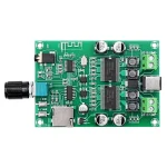
I wish to use the amp board in the picture but in my application the aux in would be hard to access. I would like to have a jumper cable permanently plugged into the aux plug so I can connect to it remotely, but doing so prevents use of Bluetooth function, even if the other end of the cable is not connected to any device.
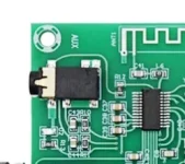
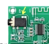
I was thinking of unsoldering the aux jack and mounting it remotely and connected to the board by wires, but that seems tricky.
Is there away I can just eliminate it from switching off Bluetooth if I use the cable as I originally intended ?
 

Attachments

  • H133316bca1c142bd9bd2adaadbe3b21e9.jpg
    H133316bca1c142bd9bd2adaadbe3b21e9.jpg
    292 KB · Views: 9
  • 20221203_020037.jpg
    20221203_020037.jpg
    22.3 KB · Views: 9
I would hazard that the jack has 4 or 5 connections on it: L, R and G, then either a separate pair of connections for a switch or maybe just one and it completes a circuit using G.

I would determine what the pinout of the connector is. Disabling the BT disconnect is likely as easy as not hooking up that switch. (or hard tying it, based on how it is used.)
 
Not always jack comes with switches. There's other ways how to sense connection.
Measure if there's any dc voltage between ground and left or right.
 
I see this (Arrow) connecting the Aux input to the BT chip. Do you think that could be it ?
 

Attachments

  • 20221203_091218.jpg
    20221203_091218.jpg
    23 KB · Views: 4
It can be. One black resistor between jack and chip going to jack ground looks suspicious.
I'd carefully cut trace with sharp blade, later you can scrape green mask and put solderbridge on naked copper.
Or unsolder the resistor.

3 pairs of capacitors and resistors under Jack seems likely a stereo inputs+ ground.
 
I was thinking the same for the three connections on the lower side (in photo) of the input jack.

There is a metal band over the front of the input jack that appears to connect to the trace that I indicated.

I have used this circuit board to power two Paradigm bookshelf speakers in a Retro style housing. We are VERY pleased with the sound.
 

Attachments

  • 20201016_175609.jpg
    20201016_175609.jpg
    114.8 KB · Views: 1
I also think it is that top trace and R12. Measure the voltage there both with a plug inserted and not.
 
During disassembly the Aux jack came partly detached from the board. So having nothing to loose I relocated the Aux into the back surface of my housing, connected by wire. Thankfully all now works well.

Thank you for your help.
 
Back
Top