What type of capacitor is this?

Joined
Mar 24, 2008
Messages
885
Location
A Warm place to live in
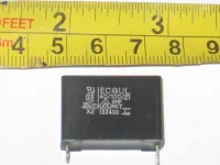
Home aircon that's 15 years old (wall mounted in the living room) won't turn on. Mitsubishi brand. Opened 'er up, removed the single printed circuit board in there. I see no bad solder joints nor any obviously bad components. Tested all the components that I could (except for the 5 ICs) - found a few resistors that tested significantly lower in value vs what they should be. Also found 3 capacitors that were open. (I used my ol' Heathkit DMM with capacitor test function.) Two were marked 0.15 and 0.047 uf, 275 volts while the other one is 0.47 uf 250 volts . What kind of capacitor are they? I was wondering if there's anything special about these capacitors. See pic below, all 3 bad capacitors are of similar build. Perhaps I can use mylar caps of similar value I may have in my parts bin to replace the bad ones?

One other thing, what does the code 40/100/21 mean?
 

Attachments

  • capacitor bad for wall aircon.JPG
    capacitor bad for wall aircon.JPG
    91.2 KB · Views: 68
Last edited:
Also found 3 capacitors that were open. (I used my ol' Heathkit DMM with capacitor test function.) Two were marked 0.15 and 0.047 uf, 275 volts while the other one is 0.47 uf 250 volts . What kind of capacitor are they? I was wondering if there's anything special about these capacitors. See pic below, all 3 bad capacitors are of similar build. Perhaps I can use mylar caps of similar value I may have in my parts bin to replace the bad ones?

One other thing, what does the code 40/100/21 mean?
Capacitors will show "open" in the Ohmic or Resistance mode.
 
Here is a datasheet. I did not see capacitance value on your sample.
 

Attachments

  • Datasheet Pana.pdf
    1.4 MB · Views: 10
Before you change parts - find out/rule out you voltage positive rail is shorted to ground and remove/replace the cause of the short(you sound like you already know this but hey).
Blown transistor or maybe a smallish cap next to a chip(or the chip itself).
Saying this, because a cap(of the X2 variety) is unlikely to solve it. It is as 930 said, probably in a filter role. As it wont start, I would check the power supply section/ stuff first.
 
Those units have inverter drive to the motors, including the evaporator fan. The AC line is power factor corrected, rectified, and chopped into three phase AC at a variable frequency and voltage for the motor. The capacitor is to filter inverter "hash" from feeding back into the power line. As others noted it is X2 rated for direct connection across a power line without exploding. Do not use something out of the junk box from an old radio.

This isn't a typical Trane etc with a split capacitor induction motor and of course everyone says "check the capacitor, it's usually the problem." You're in a completely different world here.
 
With use and time, resistors typically drift upward in value.
Capacitors can only be checked when removed from circuit (unsolder one lead).
 
I am not electronic expert but have you checked if they sell that particular Board that goes bad as a whole board?
That may be your best solution.
I know it may not be the cheapest option, though.
 
Thanks everyone for the input. The unit is old, and is not of inverter technology. As a matter of fact, the compressor is the ordinary single phase type and was replaced 6 years ago. I have checked the parts in the power supply, all look good physically. The only things I have not checked are the integrated circuit chips, including the power/voltage regulator module IC. The only reliable way I know to check them is to replace them. So now to find a 7812, NEC2501 and an L88R05D IC...

The 3 capacitors were tested with one leg desoldered from the PCB. All registered practically zero capacitance value with my DMM that has a capacitance meter function.

@yst, the 0.47uf marks are on the top of the part, not seen in the photo.
@ka9, thanks for the mylar capacitor thumbs up. I gather from yst's link the X2 uses nonflammable resin and flame retardant plastic case. I will try to find X2 type replacement, though.
@DrDanger, yes good idea to fine tooth comb the +supply rail.
 
Last edited:
For the ICs. Google their datasheets for info/pinouts, but should be easy enough to test. If you have to have mains to test use an isolation transformer or a safety lamp.

7812 - should have have 12v on pin 3(output).
L88R05D - should have 5v on pin5.
The last one is an optocoupler/isolator and is a bit harder to test. I would start by measuring each side for a 0.7-1.2v voltage drop and youtubing the video for the actual test.

Forgot to put in the usual disclaimer : only test live stuff if you are experienced/qualified.
 
Last edited:
Those units have inverter drive to the motors, including the evaporator fan. The AC line is power factor corrected, rectified, and chopped into three phase AC at a variable frequency and voltage for the motor. The capacitor is to filter inverter "hash" from feeding back into the power line. As others noted it is X2 rated for direct connection across a power line without exploding. Do not use something out of the junk box from an old radio.

This isn't a typical Trane etc with a split capacitor induction motor and of course everyone says "check the capacitor, it's usually the problem." You're in a completely different world here.
You sure know a lot about these!
 
Back
Top