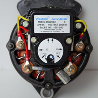
I found that the capacitor on my alternator was leaking. So I bought a replacement and changed a new one. Some people say this part is not neccessary, some say it is. Supposedly its only for suppression of RF noise. But I also heard it keeps arcing on the alternator carbon brushes to a minimum.

You are using an out of date browser. It may not display this or other websites correctly.
You should upgrade or use an alternative browser.
You should upgrade or use an alternative browser.
Alternator condensor-capacitor what does it do
- Thread starter alcyon
- Start date
MolaKule
Staff member
Sparking or the generation of an arc creates radio frequencies, just like lightning as heard on an AM radio.
If you reduce or eliminate sparking, you reduce or eliminate noise.
If you reduce or eliminate sparking, you reduce or eliminate noise.
alcyon
Thread starter
So its kinda like killing 2 birds with 1 stone. Reducing sparking also prolongs the life of the Commutator ?Sparking or the generation of an arc creates radio frequencies, just like lightning as heard on an AM radio.
If you reduce or eliminate sparking, you reduce or eliminate noise.
That's not how I understand it, rather the capacitor uF is chosen to shunt a particular frequency of noise (and higher) to ground to keep this HF noise out of sensitive circuits like the radio.
For it to reduce arcing you'd have to have multiple capacitors, across each winding and respective brush making contact.
For it to reduce arcing you'd have to have multiple capacitors, across each winding and respective brush making contact.
MolaKule
Staff member
Kinda. The capacitor acts as an electrical integrator and also "shunts" or takes RF to ground.So its kinda like killing 2 birds with 1 stone. Reducing sparking also prolongs the life of the Commutator ?
The amount of sparking at the brush/commutator is dependent on a number of variables, such as brush spring pressure, current being supplied, condition of the commutator surface (how smooth), and carbon debris.
Alternators don't have commutators they have slip rings to supply current to the rotor. They don't spark like commutators because there should be pretty much continuous contact.
its for rfi suppression and if its esr is low enough it reduces ripple.diodes do produce rfi.
in many sensitive applications each may be bypassed with a small cap.
the battery is supposed to handle the ripple though.
when ripple is not suppressed you hear a whine that varies with rpm through the radio.
in many sensitive applications each may be bypassed with a small cap.
the battery is supposed to handle the ripple though.
when ripple is not suppressed you hear a whine that varies with rpm through the radio.
MolaKule
Staff member
The regulator (in the back of the alternator) is an Integrated circuit that supplies current to the rotor field. The rotor field is rotated by engine power, so what we have is a Mechanical-to-Electrical energy conversion system. The current from the regulator is transferred to the rotor field coils via copper alloy slip rings and special graphite brushes that are in constant constant with the slip rings.


The resultant magnetic field created in the Rotor coils induce a three-phase AC voltage and current in the Stator coils that is subsequently rectified by low voltage/high current diodes. A diode turns the AC currents into DC currents.
 www.dummies.com
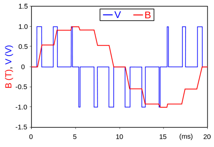
In order to control the current to the rotor, the regulator uses a regulating system called, "Pulse Width Modulation," a system that switches a pulse that varies in width. A wider pulse is generated when more voltage and current is needed and vice versa.

 www.analogictips.com
Any switching system generates noise because of the fast rise and fall times of its waveform, sometimes inducing a situation called "ringing."
A capacitor slows this fast rising and falling, mathematically integrating the waveform, thus reducing overall noise. When brushes get dirty and or when the slip rings get pitted, sparking can occur at the mating surface as well.

STATOR Fits DELCO ALTERNATOR CS144 19 21SI 22SI SERIES 140A | eBay
Find many great new & used options and get the best deals for STATOR Fits DELCO ALTERNATOR CS144 19 21SI 22SI SERIES 140A at the best online prices at eBay! Free shipping for many products!
www.ebay.com
The resultant magnetic field created in the Rotor coils induce a three-phase AC voltage and current in the Stator coils that is subsequently rectified by low voltage/high current diodes. A diode turns the AC currents into DC currents.
<b>How Power Supplies Turn AC into DC in Electronic Circuits</b> - dummies
The task of turning alternating current into direct current is called rectification, and the electronic circuit that does the job is called a rectifier . The mo
In order to control the current to the rotor, the regulator uses a regulating system called, "Pulse Width Modulation," a system that switches a pulse that varies in width. A wider pulse is generated when more voltage and current is needed and vice versa.

PWM: Pulse Width Modulation: What is it and how does it work?
Pulse Width Modulation, PWM, is a way to control analog devices with a digital output. A primary means that drives MCUs analog devices.
Any switching system generates noise because of the fast rise and fall times of its waveform, sometimes inducing a situation called "ringing."
A capacitor slows this fast rising and falling, mathematically integrating the waveform, thus reducing overall noise. When brushes get dirty and or when the slip rings get pitted, sparking can occur at the mating surface as well.
Last edited:
Not all voltage regulators are internal to the alternator, and external regulation is sought by those wishing to properly and more quickly charge deep cycling batteries. Many modify internally regulated alternators so an external regulator can control them instead.

I'm running external regulators, and temporarily have 3 decimal digital voltmeters on the field output terminals of my adjustable external regulators
I was expecting weird results due to the PWM, but they respond as expected.
I have some snap on ferrites I could use, but the system voltage I command the regulators to achieve, seems rock steady throughout most rpms, as long as batteries are not severely depleted and can suck up more than alternator can make at that rpm.
My first brief test of field current, i wanted to see if the external regulator put out constant 12v and limited amperage to rotor, but found amps increased with voltage, above 4.5v anyway, where my V meter at the time turned on.
The more recent test I did not twist power and V sense leads together, but put V sense on field output terminal and can see the V meters when driving.
I see as little as 1.7v when the alternator only needs to make 9 to 13 amps required to run my engine, with no additional loads turned on, and fully charged batteries.
.
the lower the rpm the more field voltage applied.
My Chrysler alternator has a rc-50 capacitor. the ring terminal goes over + output stud and the other hole attaches it to alternator casing( ground)
My Nippondenso alternator does not appear to have a capacitor, though I did not remove to look underneath the rectifier.

My chrysler alternator was a lifetime warranty reman. poorly reman'd. The slip rings were installed at the wrong height, the lower brush was touching both sliprings. and failed when the brush wore to touch the spot between sliprings. Surprised it worked as long as it did.
I modified brush holder to lower brushes, and honed the sliprings. They were badly out of round, and had likely been when I accepted it as a warranty replacement..
Once they were round, I polished them with 1000 then 1500 grit sandpaper wetted with Caig Deoxit d5 and never knew copper could glow like that.
I was spinning rotor to hone slip rings using a wire wheel on alternator fan, using an angle grinder speed controlled by a router speed controller.
I wonder if such a slip ring honing/polishing, can significantly increase brush life.

External Regulation Conversion - Leece-Neville 8MR Alternator - Marine How To
A Stock Leece-Neville 8MR Alternator Many boats, both power and sail, come equipped with, or have have used, the 5" small-case Motorola/Prestolite/Leece-Neville style alternator. There are literally thousands of these alternators out there. Even large Caterpillar and Cummins engines have used the
marinehowto.com
I'm running external regulators, and temporarily have 3 decimal digital voltmeters on the field output terminals of my adjustable external regulators
I was expecting weird results due to the PWM, but they respond as expected.
I have some snap on ferrites I could use, but the system voltage I command the regulators to achieve, seems rock steady throughout most rpms, as long as batteries are not severely depleted and can suck up more than alternator can make at that rpm.
My first brief test of field current, i wanted to see if the external regulator put out constant 12v and limited amperage to rotor, but found amps increased with voltage, above 4.5v anyway, where my V meter at the time turned on.
The more recent test I did not twist power and V sense leads together, but put V sense on field output terminal and can see the V meters when driving.
I see as little as 1.7v when the alternator only needs to make 9 to 13 amps required to run my engine, with no additional loads turned on, and fully charged batteries.
.
the lower the rpm the more field voltage applied.
My Chrysler alternator has a rc-50 capacitor. the ring terminal goes over + output stud and the other hole attaches it to alternator casing( ground)
My Nippondenso alternator does not appear to have a capacitor, though I did not remove to look underneath the rectifier.

My chrysler alternator was a lifetime warranty reman. poorly reman'd. The slip rings were installed at the wrong height, the lower brush was touching both sliprings. and failed when the brush wore to touch the spot between sliprings. Surprised it worked as long as it did.
I modified brush holder to lower brushes, and honed the sliprings. They were badly out of round, and had likely been when I accepted it as a warranty replacement..
Once they were round, I polished them with 1000 then 1500 grit sandpaper wetted with Caig Deoxit d5 and never knew copper could glow like that.
I was spinning rotor to hone slip rings using a wire wheel on alternator fan, using an angle grinder speed controlled by a router speed controller.
I wonder if such a slip ring honing/polishing, can significantly increase brush life.
MolaKule
Staff member
Your's is a special application but most light truck and passenger vehicles use the integral regulator.Not all voltage regulators are internal to the alternator, and external regulation is sought by those wishing to properly and more quickly charge deep cycling batteries. Many modify internally regulated alternators so an external regulator can control them instead...
I have an Amateur Radio friend who has a 100W transceiver feeding a 600W amplifier in his F250 consuming about 950 Watts of power alone just for the radio system, about 80 Amps. He uses welding cable to feed this system and the twin batteries. While he has a high current alternator, he also has an external regulator that switches in more field current when he activates the radios. You gotta see it to believe it.
Similar threads
- Replies
- 19
- Views
- 599
- Replies
- 13
- Views
- 1K
- Replies
- 31
- Views
- 1K
- Replies
- 14
- Views
- 3K
