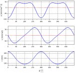
Can anyone tell me where on this graph you have dx/dΘ = 0 for any dΘ !=0 (aka "no motion")
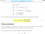
Can't see it in the graph, or even in the math on that page. Is there some dΘ where the piston motion decouples from the crank?
And if say the motion stops for 10^-20 sec, what's the oiling issue of the piston during this time? And if there is an issue, what oil property is the item to combat the wear?
 x-engineer.org
Can't see it in the graph, or even in the math on that page. Is there some dΘ where the piston motion decouples from the crank?
And if say the motion stops for 10^-20 sec, what's the oiling issue of the piston during this time? And if there is an issue, what oil property is the item to combat the wear?
Kinematic analysis of the ICE piston – x-engineer.org
Tutorial on how to calculate the postion, the relative and mean speed and the accleration of an ICE piston function of the crankshaft angle
x-engineer.org
")